Carrier 38AH024-034 User Manual
Page 11
Attention! The text in this document has been recognized automatically. To view the original document, you can use the "Original mode".
TO OTHER COMMUNICATING
THERMOSTATS
CARRIER COMMUNICATING
TEMP MONITOR
THERMOSTAT
{MODEL MS(T)OIES)
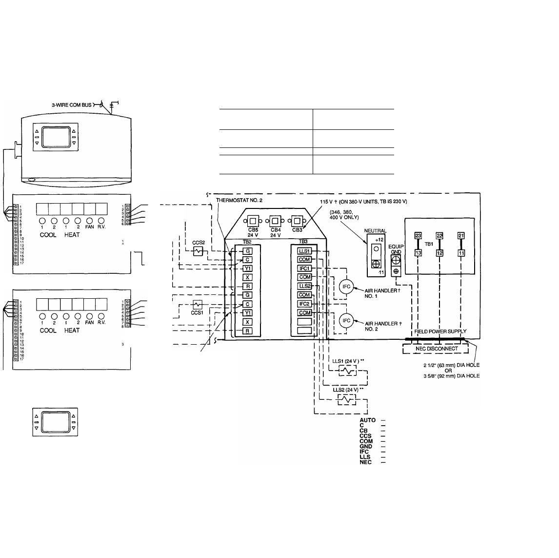
*CB3 protects control circuit at the following unit voltages;
CONTROL CIRCUIT
PROTECTED AT:
(V-Ph-Hz)
UNIT (V-Ph-Hz)
208/230-3-60
115-1-60
460-3-60
575-3-60
230-1-60
380-3-60
230-3-50
230-1-50
346-3-50
400-3-50
fuse Carrier accessory part no. 40RR900181 for indoor-
fan contactor.
"Install LLS valve no. 1 on the liquid line of the air handler
controlled by the 38AH circuit no. 1 thermostat. Install
LLS valve no. 2 on the liquid line of the air handler con
trolled by the 38AH circuit no. 2 thermostat.
NOTES:
1. Capacity control solenoid and liquid line (solenoid drop
refrigerant control) valves are field supplied.
2. CB4 protects TBS circuit; CBS protects TB2 circuit.
3. On the TSR-01 Relay Pack, the outside-air sensor, supply-
air sensor, and direct expansion coll sensor are avail
able as options.
FAN
HEAT 2-----
HEAT1------
COOL 2----------
8 0 COOL 1------------------ 1
24 VAC — —
(COMMON)
TSR-01 RELAY PACK (MAXIMUM CONTACT
LOAD IS 1 AMP AT 24 V) (SEE NOTE 3.)
FAN-------
HEAT 2 —
HEAT1 —
COOL2
-
COOL1- -
1
|I®1 24 VAC
^111^—24 VAC —
(COMMON)
TSR-01 RELAY PACK (MAXIMUM CONTACT
LOAD IS 1 AMP AT 24 V) (SEE NOTE 3.)
3-WIRE COM BUS
TO OTHER COMMUNICATING
THERMOSTATS
CARRIER COMMUNICATING
TEMP MONITOR
THERMOSTAT
(MODEL MS(T)OIES)
THERMOSTAT NO. 1
LEGEND
R.V.
TB
Automatic Changeover
Contactor, Compressor
Circuit Breaker
Capacity Control Solenoid
Common
Ground
Indoor-Fan Contactor
Liquid Line Solenoid
National Electrical Code
^.S.A. Standard)
Reversing Valve
Terminal Block
Thermostat, Cooling
Field Accessory Wiring
Field Control Wiring
Factory Wiring
Field Power Wiring
Indicates Common
Potential; Does
Not
Indicate Wiring
Fig. 8 — Typical Wiring Schematic — Unit 38AH with 2 Air Handlers