Winter start control, Head pressure control, Fig. 15 — capacity control valve – Carrier 38AH024-034 User Manual
Page 20: Table 5 — fan cycling controls
Attention! The text in this document has been recognized automatically. To view the original document, you can use the "Original mode".
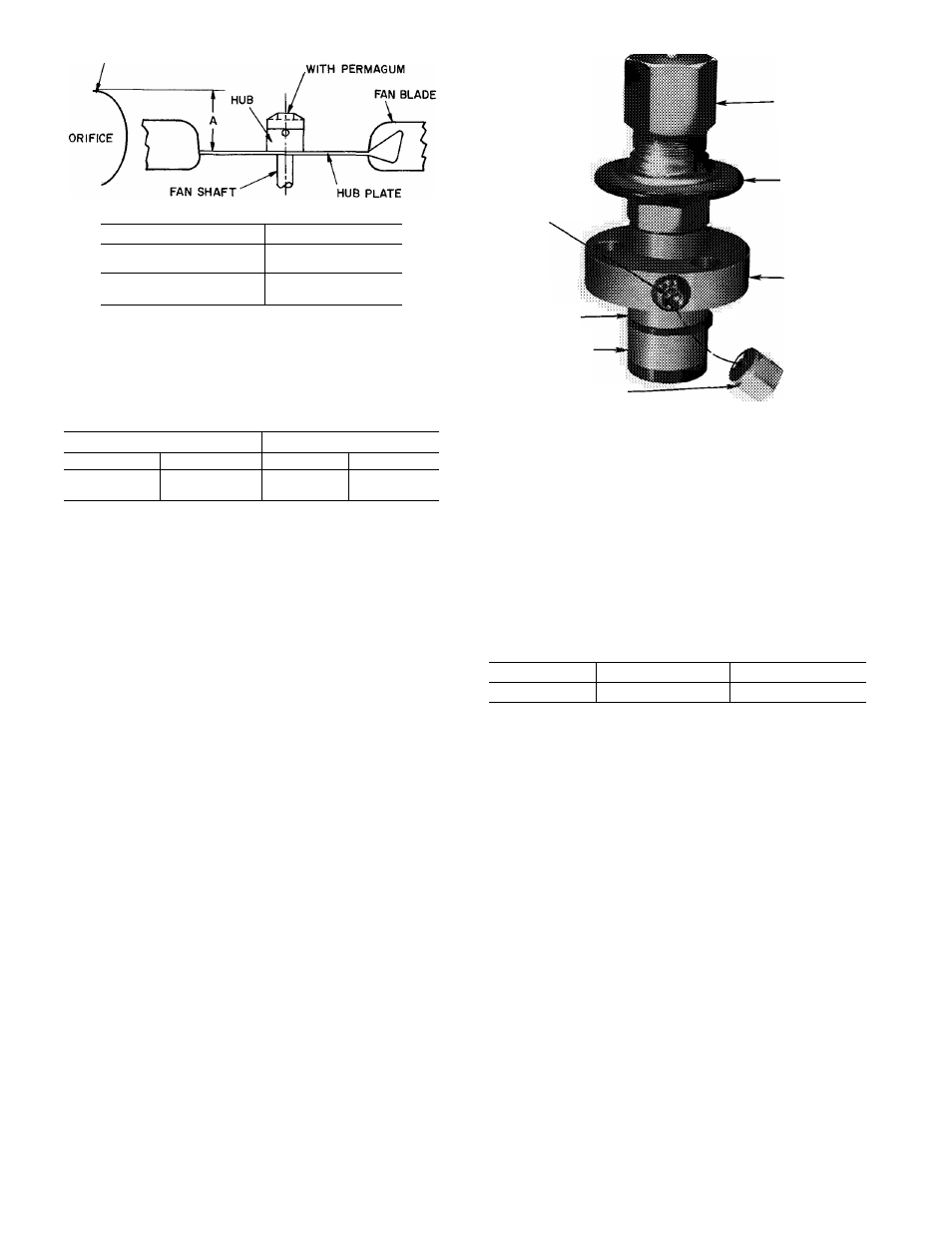
TOP OF FAN ORIFICE
FILL HOLE IN FAN HUB
PROP LOCATION
“A” in. (mm)
60 Hz
38AH024-034
3.5 (89)
50 Hz
38AH024-034
4.3 (109)
Fig. 14 — Location of Prop on Motor Shaft
from Outside of Orifice Ring
Table 4 — Pressure Switch Settings, psig (kPa)
HIGH PRESSURE
LOW PRESSURE
Cutout
Cut-in
Cutout
Cut-in
426 ± 7
320 ± 20
27 ± 3
44 ± 5
(2937 ± 48)
(2206 ± 138)
186 ± 21)
(303 ± 34)
PRESSURE
DIFFERENTIAL
ADJUSTMENT
SCREW
CONTROL
SET POINT
ADJUSTMENT
-NUT
POWER HEAD
VALVE BODY
BYPASS
PISTON RING
BYPASS PISTON
DIFFERENTIAL SCREW
SEALING CAP
(CAP MUST BE REPLACED
TO PREVENT REFRIGERANT LEAKAGE)
Fig. 15 — Capacity Control Valve
Winter Start Control
— Purchase accessory Carrier
part no. 38AE900021 for winter start control.
Head Pressure Control
— Control allows system to
operate at full capacity under low ambient temperature
conditions.
FAN CYCLING — These 38AH units have standard pro
vision for fully automatic intermediate-season head pres
sure control through condenser fan cycling. Fan no. 2 is
cycled by an outdoor-air thermostat which responds to out
door ambient temperature. The thermostat is loeated in the
lower divider panel between the compressor compartment
and condenser section. Through a hole in the panel, the
sensing element is exposed to air entering the no. 1 fan
compartment. Fan no. 1 is non-cycling. Table 5 shows the
operating settings of the air temperature switch.
Table 5 — Fan Cycling Controls
CONTROL BY
SWITCH OPENS
SWITCH CLOSES
Temp — F (C)
60 ± 3 (15 6 ± 1.7)
70 ± 3 (21.1 ± 1.7)
NOTE: See Fig. 6 for fan arrangement.
20