Iz^j-i, O[^o[^o – Carrier 38AH024-034 User Manual
Page 10
Attention! The text in this document has been recognized automatically. To view the original document, you can use the "Original mode".
3-WIRE COM BUS
! TO OTHER COMMUNICATING
f THERMOSTATS
CARRIER COMMUNICATING
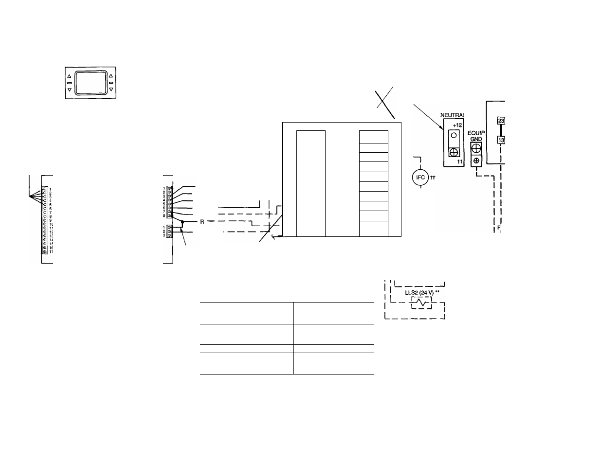
TEMP MONITOR
THERMOSTAT
(MODEL MS(T)OIES)
o[^o[^o[^
115 V t (ON 380-V UNITS. TB IS 230 V)
(346, 380,
400 V ONLY)
CB5
24 V
CB4
24 V
CB3
r
0 o o o o o
1
2
1
2 FAN R.V.
COOL HEAT
TSR-01 RELAY PACK (MAXIMUM CONTACT
LOAD IS 1 AMP AT 24 V) (SEE NOTE 3.)
HEAT 2
HEAT1
COOL 2
COOL1
24 VAC -
(COMMON)
TB2
TB3
[H
I
llsi
1-
■“I
[C]
ICOMh
“1
—
--[
y
T]
IlFClh
_
S
fCOMh
ra
1
as
2
|--
11
—
-d]
ICOMh
1
—
--d]
1IFC2 1
'
--En]
ICOMi
1
S
1 ll
( 1
~C
r
]
1 1'
ll
J_L,
24 VAC (R)
THERMOSTAT*
AUTO
C
CB
COM
GND
IFC
LLS
NEC
R.V.
TB
TC
LEGEND
Automatic Changeover
Contactor, Compressor
Circuit Breaker
Common
Ground
Indoor-Fan Contactor
Liquid Line Solenoid
National Electrical Code
(U.S.A. Standard)
Reversing Valve
Terminal Block
Thermostat, Cooling
Field Accessory Wiring
Field Control Wiring
Factory Wiring
Field Power Wiring
Indicates Common Potential;
Does Not Indicate Wiring
*Use thermostat wiring shown here for single air-handler
applications.
tCB3 protects control circuit at the following unit voltages:
CONTROL CIRCUIT
PROTECTED AT:
(V-Ph-Hz)
UNIT (V-Ph-Hz)
208/230-3-60
115-1-60
460-3-60
575-3-60
230-1-60
380-3-60
230-3-50
230-1-50
346-3-50
400-3-50
“I
I
___ I
TB1
LLS1 (24 V)*
Iz^j-i
ELD POWER SUPPLY
NEC DISCONNECT J
2 1/2” (63 mm) DIA HOLE
OR
3 5/8" (92 mm) DIA HOLE
**For a single air handler, LLS valve no. 1 is to be used on the lower
(no. 1) evaporator circuit. The LLS valve no. 2 is to be used on the
upper (no. 2) evaportor circuit.
ttOnly one indoor-fan contactor is required on single air-handler
applications. Use Carrier accessory part no. 40RR900181 for indoor-
fan confacfor.
NOTES:
1. CB4 protects TB3 circuit; CBS protects TB2 circuits.
2. LLS1 and LLS2 are field supplied.
3. TB2 and TB3 are in 24-v circuits.
4. On the TSR-01 Relay Pack, the outside-air sensor, supply-air
sensor, and direct expansion coil sensor are available as
options.
Fig. 7 — Typical Wiring Schematic — Unit 38AH with Single Air Handler