VACUUBRAND PC 600 LAN NT User Manual
Page 34
page 34 of 102
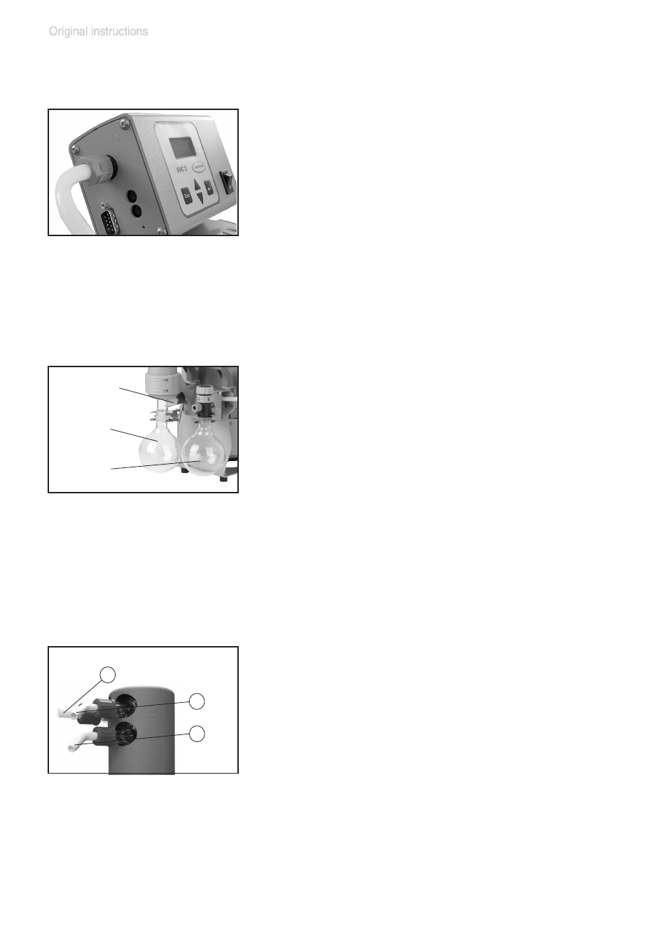
Connection of components at the controller
At the side of the controller are the serial in-
terface RS-232 C and VACUU•BUS jacks for
connection of accessory components: in-line
valve / coolant valve / external pressure trans-
ducer / external venting valve / etc.
+
Plug the VACUU•BUS lines of accessory
components into the VACUU•BUS jacks. Do
not apply off-axis forces when assembling
or removing plug connections! Observe cor-
rect orientation of the plugs.
Catchpots:
The catchpot at the inlet protects against drop-
lets and particles from entering the pump.
+
Enhances lifetimes of diaphragms and
valves.
+
Improves vacuum performance in applica-
tions with condensable vapors.
Both catchpots are coated with a protective
layer to protect against shattering in case of
breakage or implosion.
➨
Assemble the catchpots at the inlet and at
the outlet using joint clips.
Exhaust waste vapor condenser:
➨
Assemble the hose nozzles for coolant inlet
(12) and coolant outlet (13) tubing at the ex-
haust waste vapor condenser.
The exhaust waste vapor condenser enables
an efficient condensation of the pumped va-
pors at the outlet.
+
No backflow of condensates.
+
Controlled recovery of condensates.
+
Close to 100% solvent recovery.
+
The isolation cover protects against glass splinters in
case of breakage, acts as thermal isolation to avoid
catchpot at
the outlet
catchpot at
the inlet
(9)
overpressure
safety relief
device
outlet (gas!)
2
12
13