Initial test and configuration – USL LSS-100 User Manual
Page 6
LSS−100P Installation & Operation Manual
6
Figure 3 - LSS-100P Graph
Initial Test and Configuration
It is a lot easier to do the initial testing of the LSS-100P on a table or the floor of the projection booth
instead of on top of a ladder.
1. Connect power to the LSS-100P. This can be done using a standard USB to mini-USB cable and
the included USB power supply. A standard cable can also be used to power the LSS-100P from a
USB jack on a computer. If such a cable is not available, connect the supplied USB cable to the
supplied adapter board as shown in figures 4 and 5 (different cables use different colors).
Terminal Wire Color Wire Color
+5V
Red
Red
A
Blue
White
B
Yellow
Green
C
none
none
Ground
Black
Black
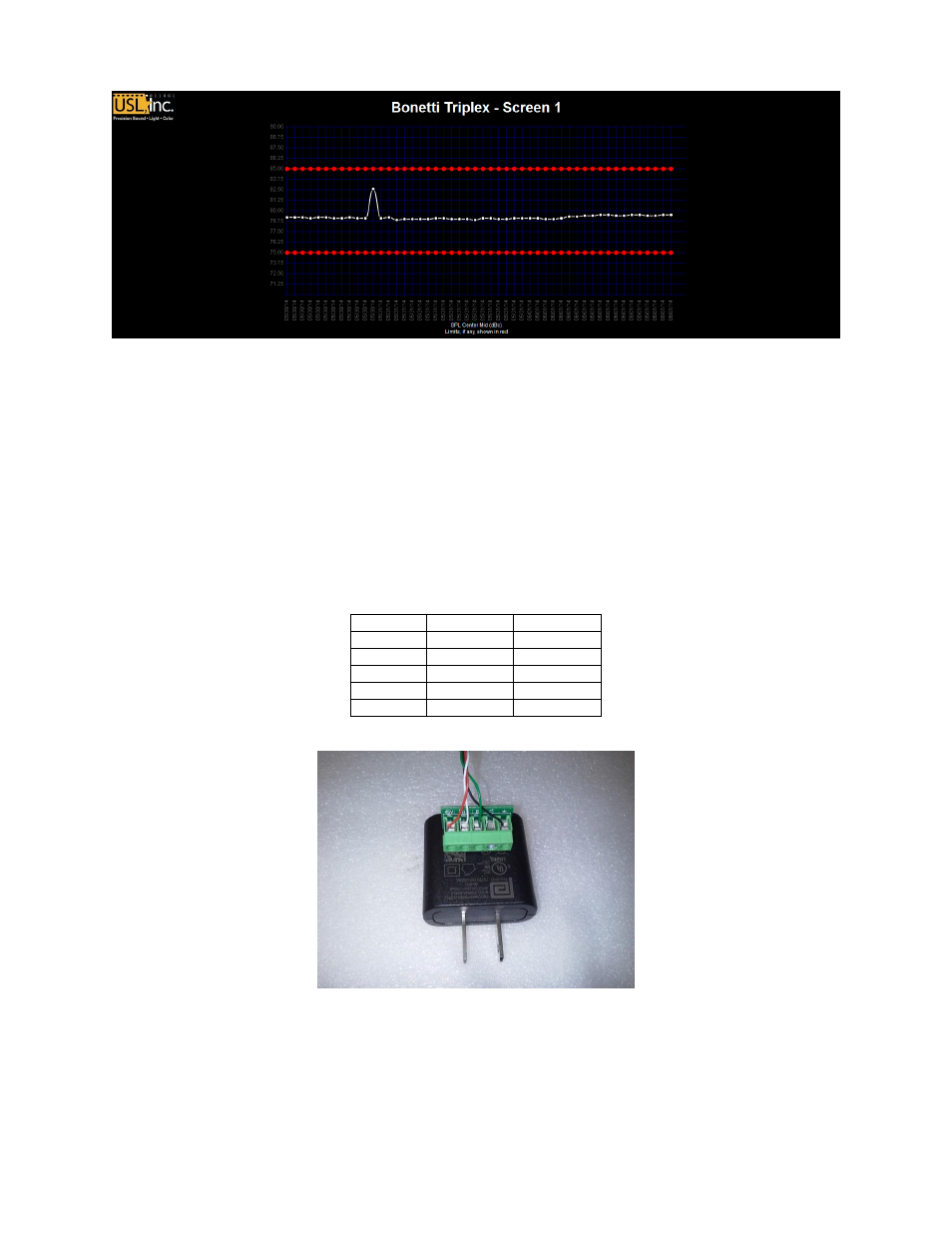
Figure 4 - USB Adapter Pin-Out
Figure 5 - USB Adapter Wiring
Note orientation of adapter in USB power supply (terminals down).
2. The green LED next to the Ethernet connector on the LSS-100P will light dimly for 30 seconds,
then light brightly. During this time, the LSS-100P is checking its backup copy of the system
firmware. The green LED is lit whenever the LSS-100P is powered unless the flash memory chip