TriangleTube Prestige Cascade System User Manual
Page 29
SECTION V – CSD-1 INSTALLATION
If local codes require the installation to comply with CSD-1,
the addition of high limit control(s) and low water cut off con-
trol(s) are required. The quantity and location of the controls
vary depending on the installation.
P/S or R/R with Valves Kit – PSCAS17
In these installations the boilers can be individually iso-
lated and therefore both a high limit control and a low
water cut off control are required for each boiler. An
optional kit PSCAS17 is required for each boiler, see
Table 7, page 19 for a breakdown of kit components.
1. The high limit control will need to be installed in the
supply piping directly below the boiler. Remove
1/2” NPT plug in supply piping and install drywell
from PSCAS17 kit.
2. Install sensing bulb of the high limit control with heat
conductive compound into the drywell, both the limit
and heat conductive compound are supplied in the kit.
3. Secure limit to well using clamp supplied with limit.
4. Low water cut off control for each boiler will need to
be positioned above the boiler combustion chamber.
5. The standard field installed air vent and pressure
relief valve configuration will need to be reposi-
tioned, see Figure 27.
26
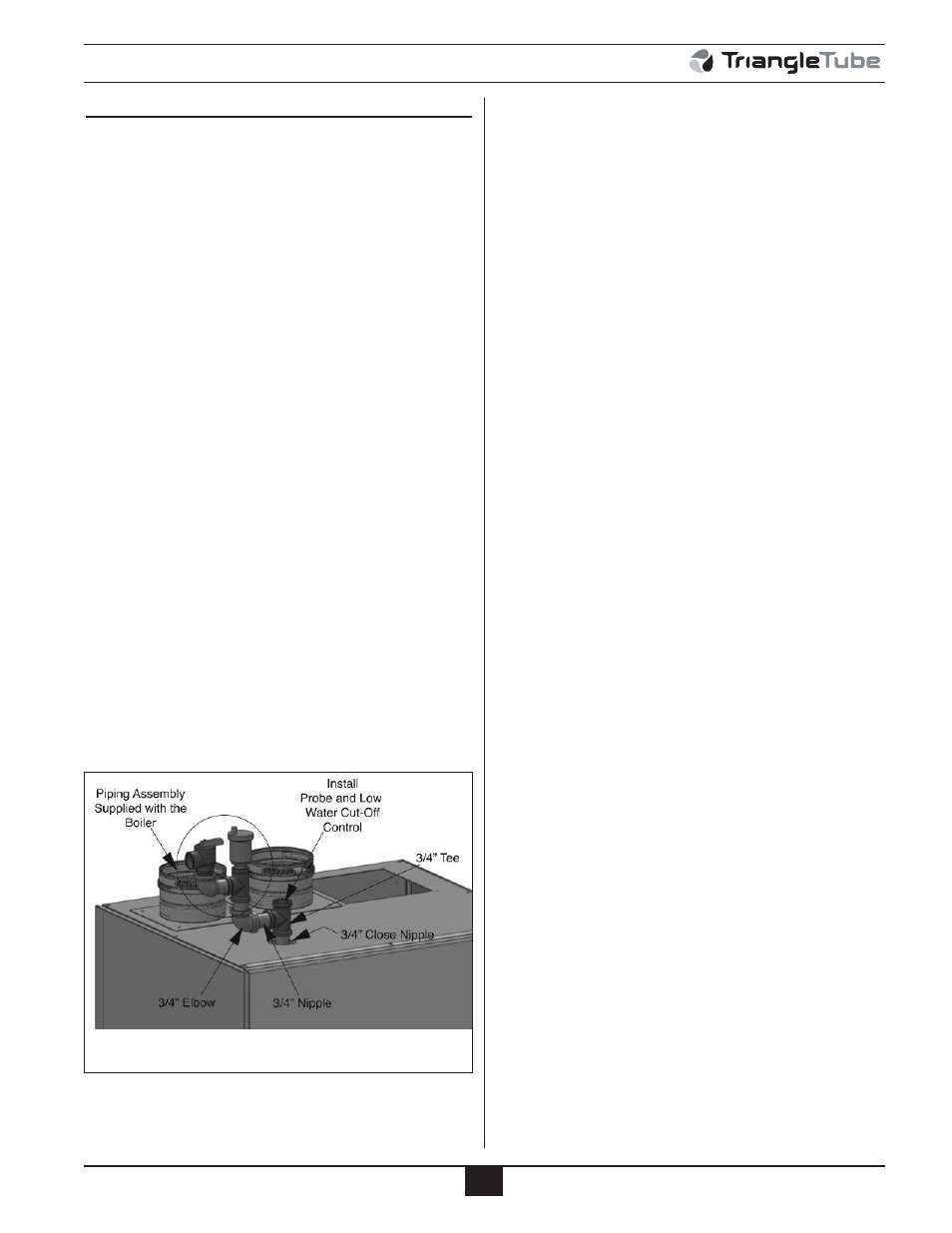
CSD-1 Piping & Control Installation
6. A ¾” NPT brass tee will need to be installed at the
top of each boiler utilizing ¾” NPT brass close nip-
ple, both supplied in kit. Install tee with the branch
portion facing horizontally.
7. Low water cut off control and probe supplied in the
kit should be installed vertically in the top flow
through portion of tee.
8. A ¾” NPT brass nipple should be installed in the
branch portion of the tee along with a brass ¾” NPT
90 degree elbow, both supplied in kit.
9. The standard field installed air vent and pressure relief
valve configuration (supplied with the boiler) should
be installed in the top of elbow, see Figure 27.
Reverse Return (R/R)
In this installation a shut off valve will need to be
installed on both the system supply and return connec-
tions. A drain should also be installed before the system
return shut off valve. In this configuration the boilers
cannot be individually isolated therefore a single low
water cut off and manual high limit will be required in
the system supply piping before the system supply shut
off valve. The low water cut off must be installed in the
system piping above the boilers. The low water cut off
with probe and manual high limit and dry well can be
field supplied or ordered separately, see page 45 for part
number.
Fig. 27: Low Water Cut-Off Installation