TriangleTube Prestige Cascade System User Manual
Page 25
SECTION III – INSTALLATION
Distribution Manifold
1. Place the distribution manifold in the location to be
installed. If a Hydronic Junction is utilized consider-
ation must be made in determining location.
2. Level distribution manifold .
3. Secure manifold to floor. To secure the manifold to
the floor, drill and install anchors (supplied with
Cascade) in floor through the holes in the legs of the
distribution manifold, one per leg.
For optimum support of the weight of the Cascade it
is recommended to secure the distribution manifold
to the floor, especially when utilizing multiple distri-
bution manifolds.
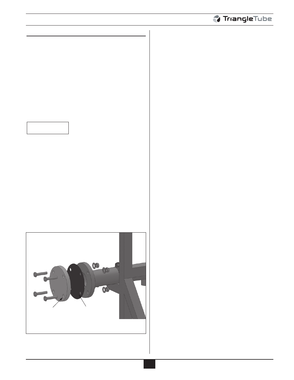
4. Install blind flange (seal plate) on the distribution
manifold with gasket and hardware supplied, see
Figure 22. For primary secondary applications, this
flange should be installed on the distribution mani-
fold on the end opposite to the hydronic junction.
For reverse return applications the top blind flange
should be installed opposite of the system supply
piping. Install the bottom blind flange opposite of
the system return piping, which is also opposite the
top blind flange.
BEST PRACTICE
22
Installation
5. Install ANSI to 3” NPSC connection flanges to the
system supply (top) and system return (bottom) con-
nections utilizing the gasket and hardware supplied.
Multiple Distribution Manifolds
The maximum number of boilers that can be piped using
multiple Cascade Distribution Manifolds is five. When
connecting multiple manifold a 2 Boiler Distribution
Manifold with another 2 Boiler Distribution Manifold or
with a 3 Boiler Distribution Manifold, utilize the gas-
kets and hardware supplied in kits to join the two mani-
folds.
Blind Flange
Gasket
Fig. 22: Blind Flange Manifold Installation