Top Flite KittiWake User Manual
Page 6
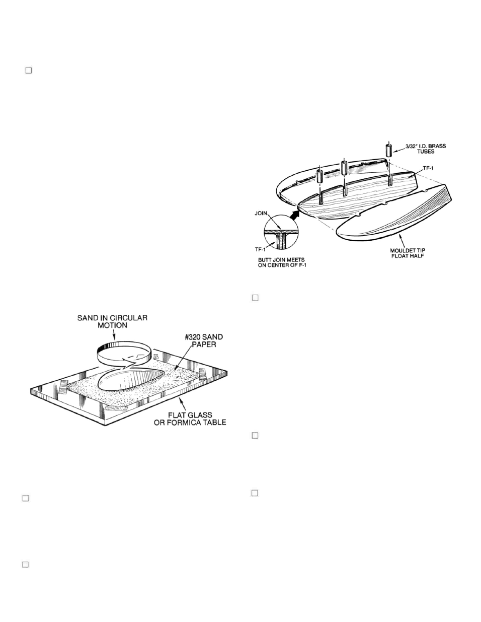
1. As shown in the cross-section diagram, the tip
float has to be cut from it's base. The easiest way
to do this with absolute accuracy is to make a sim-
ple cutti ng tool. We use a 4 "-5" length of 1/8" x 3/8"
spruce or hard balsa to which we glue a #11 X-acto
blade, flat, to one end of this stick with about one
half of the blade's length protruding past the end
of the stick. When this tool is laid flat on the
bench, it can provide a consistently accurate cut
1/8" above the work surface. Use a flat formica
table top for this operation. Select one of the tip
float halves and place flat on the table and hold it
firmly to the table with one hand. With your other
hand, slide the X-acto tool all around the tip float,
scoring it lightly as you go. Repeat this operation
several times until you have a definite score line
all around the piece. You should now be able to
flex the plastic at the score line until it breaks
free. Repeat this procedure with the remaining
float halves.
halfway into the center—take your time to
achieve a good fit. Once satisfied, locate the six
required lengths of brass tubing from the parts
bag in your kit. Lay the TF-1's flat on a protected
work surface and epoxy one of the tubes into each
of the slots provided. Be sure the tubes are laying
flat and that glue does not get into them and allow
to cure completely. When dry, lightly sand the
tops of these tubes flush with the top edges of the
TF-1 cores.
tubes provide mounting capability to the wing. The
secret to success here is the accurate cutting of the tip
float halves from their bases, thus providing a nice,
straight edge at the center.
2. As shown, the edges of each tip float should now
be sanded lightly to absolute flatness. A piece of
#320 sand paper taped to a piece of glass or a for-
mica table top will work great for this purpose.
Simply hold the tip float half on the sandpaper
and move it lightly in a circular motion. Just a few
passes will be needed.
3. Locate and remove the two required TF-1 light-ply
cores from their die-cut sheet. These cores now
need to be final sanded to fit exactly into the
center of the tip float halves. They only need to fit
4. In this step you are going to glue the TF-1 cores
halfway into one of the tip float halves. We sug-
gest using a slow-setting CA adhesive for this
operation. Use your finger to apply a liberal
amount of glue around the inside center edge of
the tip float half. Now carefully insert the TF-1
core halfway into the float half and lay the
assembly down on your protected work surface
(core side down) and allow to cure. Once the glue
has set, pick up the assembly and inspect it for
any glue runs, etc. These can be quickly removed
with a single edge razor blade. Once satisfied,
trial fit the other float half in place—it should fit
accurately, even if a little pressure is required to
do so. Remove the remaining unglued half.
5. Use a 3/32" dia. drill bit to carefully open up the
ends of each of the brass tubes. The remain ing tip
float half can now be glued in place. Again apply
glue all around the inside center edge of the part
and press it in place. Tape or hold the assembly
until cured.
6. Once again use the 3/32" drill bit to clear-out the
holes in the brass tubes. The now-assembled tip
floats should be lightly sanded along the center
joint with #320 paper to true them. Some filling
may be required along this joint and for this we
would suggest something like lacquer putty (pro-
bably the best choice), available at most
automotive paint supply outlets. On our pro-
totypes, we used both PIC's "Pie N' Patch" filler
and Model Magic Filler with great results. Finally,
we suggest wet-sanding the floats with #600
paper prior to painting. These floats can be
6