Full size dihedral gauge forw1-a&w1-b – Top Flite KittiWake User Manual
Page 3
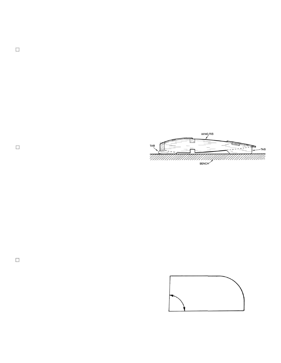
1. From their die-cut sheets, carefully remove all
wing ribs, W-1 (A and B) through W-8. Where
necessary, use a #11 blade to free the parts, mak-
ing very sure that bottom tabs remain attached.
(These have been partially cut through for later
removal, should one break off, reattach it with a
spot or two of glue). If needed, lightly sand the
edges of the ribs to remove any burring. Locate
and remove die-cut (ply) parts W-9 and W-10. Addi-
tionally, locate and have ready the four 1/
4 " x 3/8"x
24"wing spars, the two 3/8 x 3/4" x 24" leading
edges and the two 1/8" x 1/4" x 36" sub spars—all
balsa. Of course, as we proceed with these in-
structions, you will need wing sheeting
(1/16"balsa) from the stock provided in your kit.
Protect your plans with clear food wrap or
MonoKote® backing. We will build the center
section first, followed by the outer panels.
2. Cut two 2 11/16" lengths of 1/4" x 3/8" spar stock (Im-
portant: cut one of these lengths from one piece
of spar stock and the other piece from a different
length of spar stock). From one of the leading
edge pieces, cut a 2-11/16" piece. Accurately pin one
of the spar pieces directly over the plans. Now
securely pin the two rear W-1 B's in place against
the spar, making sure that they are perfectly ver-
tical to your work surface (use a triangle or block
to be sure). Now set the W-9 dihedral brace in
place on the work surface, against the bottom
spar and the two W-1 B's. Like the W-1 B's, ac-
curately position and securely pin the forward
W-1A's in place against the W-9 brace. With the
above securely in place, glue the 2-11/16" piece of
leading edge stock to the front of each W-1A (do
not glue to the break-away tabs). Now carefully
glue the top length of spar stock in place to the
W-1 B's. Starting from the leading edge, cut, fit
and glue all of the center-section's 1/16" balsa
sheeting in place; allow to dry.
3. Carefully remove this assembly from your work
surface. Unpin the short length of spar stock from
your work surface. Turn the assembly over and
epoxy W-10 in place against the rear face of the
leading edge and up against the top sheeting.
Carefully glue W-9 in place against the W-1A's and
B's, the top spar and sheeting. Take care here to
wipe-off any excess adhesive on the outer sur-
faces of the ribs and W-9. Glue the remaining
length of spar stock in place against W-9 and to
the W-1 B's. Carefully remove the bottom rib tabs
from each rib section and use a sanding block to
smooth the bottom of this structure as well as
bevel the bottom rear edge of the top sheeting.
From the kit, locate the shaped basswood wing
bolt insert. As shown, this part fits in place be-
tween the W-1 B's, about 3/8" ahead of the trailing
edge. Sand the insert as needed to fit and when
satisfied, epoxy in place. The bottom of this struc-
ture is now sheeted with 1/16" balsa from the
leading edge back to the trailing edge. Do this ac-
curately and neatly. Use a small sanding block to
now smooth the rib/sheeting joints, keeping the
outer surfaces of W-1A and B flat.
(Note: The following outer wing panel construc-
tion steps assume that both the left and right
panels are built simultaneously. Also, this is the
point at which your decision about installing the
landing gear option, shown on the plans, should
be made. The patterns provided on the plans for
rib reinforcement parts RR-1 through RR-3 should
be used to make the 1/16" Ply parts and these
should now be epoxied in place to the concerned
ribs.)
4. Use the full cross section of the wing, the view
directly beneath the wing plan, to now accurately
cut and bevel the top and bottom 1/4" x 3/8" spars
and the
3/8"x3/4"
leading edges. You'll note that the
inboard W-1 ribs are angled to provide the needed
7/8" dihedral for each wing panel. In order to pro-
vide this angle uniformly to each W-1 rib section,
we've provided you with a dihedral guage, shown
here. Use this as a pattern to now makethis guage
from either scrap ply or balsa. As you did for the
center section, now pin the bottom spars ac-
curately in place over the plans. Take care here to
ensure that they are in place straight. These bot-
tom spars are only in place for accurate rib align-
ment at this time.
FULL SIZE
DIHEDRAL GAUGE
FORW1-A&W1-B
sells a pre-bent, tempered aluminum landing gear that
mounts directly to the fuselage, at the forward float leg
location. Ken Willard has used this variation quite suc-
cessfully (see RCM Magizine, November, 1986). The
following instructions assume the float plane version
only.
3