Top Flite KittiWake User Manual
Page 11
aluminum float legs. Use a ruler, triangle and a
sharpened nail (or scribe) to accurately mark the
vertical centerline on both float legs. Now use a
soft pencil and a ruler to mark the fuselage's
centerline of both of the F-7 ply plates, on the bot-
tom of the fuselage. Use a small amount of CA
glue to now tack glue the as-yet unbent float legs
accurately in place on the bottom of the fuselage,
carefully lining up the centerlines. Now mark the
hole locations directly on the float legs and with a
7/64" dia. drill bit, drill these holes through the
aluminum, F-7 and 1/4 " ply mounting blocks. One
at a time, apply epoxy to the edges of the blind
mounting nuts and, using a screwdriver and the
#4-40 bolt, cinch the glued nut down into the hole,
from the inside. Once all four nuts have been in-
stalled in this manner, carefully remove the tack
glued float legs from the fuselage.
The next thing to do at this time is to make all the
necessary provisions for mounting the rudder,
elevator and throttle servos. As shown, we have
mounted the servos as far back in the radio com-
partment as possible and close to the bottom of
the top sheeting. We used the radio
manufacturer's stock servo mount (plastic),
which allowed for all three servos to be mounted
side-by-side. However, there's plenty of room for
the throttle servo to sit ahead of the other two, as
shown on the plans. Doing this now makes servo
installation later a simple matter of a few screws.
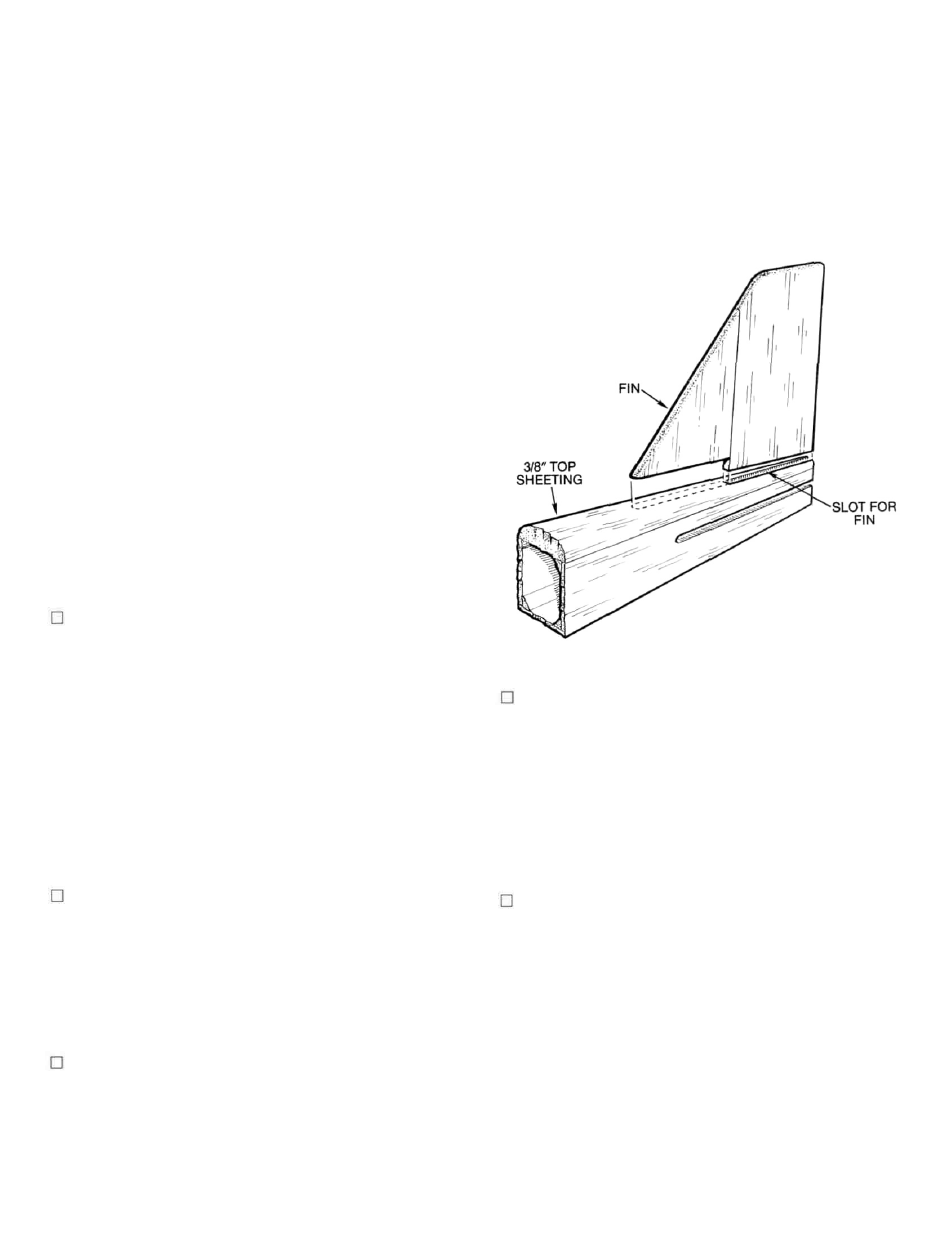
14. From your kit, locate the 3/8" x 3" x 30" balsa sheet
used for the top fuselage sheeting. Sand the front
edge to match the rear edge of the noseblock,
already in place. Cut and sand the rear edge to
match the tailpost angle. As shown, a 3/16"x 2" slot
should now be cut in the rearto provide for moun-
ting the fin. Hold the sheet accurately in place to
the fuselage and use a soft pencil to mark the
fuselage outline on it. Use a jigsaw to remove the
excess material. Glue the top sheet in place to the
top of the fuselage and rear of the top noseblock.
Lay the assembly upside down on the bench and
weight in place until dry. Once dry, use a sanding
block to smooth the edges flush with the fuselage
sides.
15. The fuselage can now be shaped and sanded to
final configuration, using the plans and cross
sections for reference. We'd suggest first using a
sharp razor plane to rough shape the fuselage,
followed by progressively lighter grades of sand-
paper to achieve final shape and surface
smoothness. Take your time here to get those
sexy lines that you admired so much in both the
ads and the box art!
16. With the wing bolted in placetothe fuselage,trial-
fit the stabilizer in place in the slot provided. Set
the assembly flat on atable and step back to sight
down the front of the model—everything should
look straight. If it isn't, some sanding and adjust-
ment of one of the slot sides may be needed. If so,
do this now. Next, be sure that the stabilizer, when
viewed from the top, is squarely in position
relative to the wing. Use a piece of string or a ruler
to be sure that the distance from one wingtip to
the tip of the stabilizer is the same measurement
on each side. Glue the stabilizer in place and
allow to dry. Next, the fin is glued in place. Again
make sure that the fin is absolutely vertical to the
stabilizer and wing. Tape and/or pin in place and
allow to dry.
17. Locate and remove die-cut sub-fin R-3. This part
has a "lobe" on it's forward end which should
now be sanded-off to match the plans. Tape the
rudder in place to the fin. Trial-fit R-3 in place to
the bottom rear of the fuselage. It's rear edge
should match the rudder's angle and depth at this
point. Once satisfied, glue R-3 in place (leave the
rudder taped to the fin). Once the glue has dried,
use a sanding block to match the R-3 sub fin to the
rudder shape. Use sandpaper to round R-3 to
shape (see E-E).
18. The engine compartment opening is now made.
We suggest starting with a small hole over what
would be the top of the engine's head and working
outward from there. The idea here is that you want
the opening to be large enough to fit the engine in
place (at this point; without the muffler mounted
yet) by hand, but not overly large. Once you can fit
the engine in and out of the opening, try the motor
mount. With access through the spinner ring
(F-4), bolt the motor mount firmly in place to the
firewall. Now fit the engine in place to the motor
mount. Slide the engine forward and attach the
spinner (we use the stub of an old 9 x 6 prop for a
spacer). Now slide the engine back until the back
of the spinner contacts the F-4 spinner ring. With
a few scraps of 1/32" material (balsa or ply), space
11