Top Flite TOPA0140 User Manual
Page 7
IMPORTANT BUILDING NOTES
•
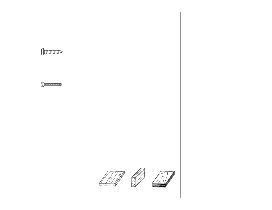
There are two types of screws used in this kit.
Sheet metal screws are designated by a
number and a length.
For example #6 x 3/4" [19.1mm]
Machine screws are designated by a number,
threads per inch and a length.
For example 4-40 x 3/4" [19.1mm]
•
When you see the term
test fit in the
instructions, it means that you should first
position the part on the assembly without using
any glue, then slightly modify or
custom fit the
part as necessary for the best fit.
•
Whenever the term
glue is used you should rely
upon your experience to decide what type of
glue to use. When a specific type of adhesive
works best for that step we will tell you what type
of glue to use.
•
Whenever just
epoxy is specified you may use
either 30-minute epoxy or 6- minute epoxy.
When 30-minute epoxy is specified it is highly
recommended that you use only 30-minute (or
45-minute) epoxy because you will need the
working time and/or the additional strength.
•
Occasionally we refer to the
top or bottom of the
model or
up or down. To avoid confusion, the
top or bottom of the model is as it would be
when the airplane is right side up and will be
referred to as the top even if the model is upside
down during that step,
i.e. the top main spar is
always the top main spar even if the wing is
upside down when you are working on it.
Similarly,
move the former up means move the
former toward the top of the fuselage even if the
fuselage is upside down when you are working
on it.
•
When you get to each step, read that step
completely through to the end before you
begin. Frequently there is important information
or a note at the end of the step that you need to
know before you start.
•
Photos and sketches are placed ahead of the
step they refer to. Frequently you can study
photos in following steps to get another view of
the same parts.
COMMON ABBREVIATIONS
Deg = degrees
Elev = elevator
Fuse = fuselage
" = inches
LE = leading edge
Ply = plywood
Stab = stabilizer
TE = trailing edge
LG = landing gear
mm = millimeters
TYPES OF WOOD
BALSA BASSWOOD PLYWOOD
GET READY TO BUILD
1. Unroll the plan sheets. Roll them inside out so
they lie flat.
2. Remove all the parts from the box. Use a
ballpoint pen (not a felt tip pen) to lightly write the
name or size on each piece so you can identify it
later. Use the
die-cut patterns on pages 8 & 9 to
identify and mark the die-cut parts before you
remove them from their die sheets. Many of the
parts already have numbers stamped on them, but
in some cases the number is located alongside the
parts. You may remove all the die-cut parts from
their die sheets now or wait until you need them. If a
part is difficult to remove, don’t force it out but cut
around it with a #11 blade. After you remove the
parts from their die sheets, lightly sand the edges to
remove slivers or die-cutting irregularities. Save
some of the larger scraps of wood.
3. Separate the parts into groups such as stab,
fin, wing, and fuse. Zipper-top food storage bags
are handy to store parts in as you sort, identify and
separate them into subassemblies.
1/64" = .4mm
1/32" = .8mm
1/16" = 1.6mm
3/32" = 2.4mm
1/8" = 3.2mm
5/32" = 4mm
3/16" = 4.8mm
1/4" = 6.4mm
3/8" = 9.5mm
1/2" = 12.7mm
5/8" = 15.9mm
3/4" = 19mm
1" = 25.4mm
2" = 50.8mm
3" = 76.2mm
6" = 152.4mm
12" = 304.8mm
15" = 381mm
18" = 457.2mm
21" = 533.4mm
24" = 609.6mm
30" = 762mm
36" = 914.4mm
METRIC CONVERSION
1" = 25.4mm (conversion factor)
- 7 -