Top Flite TOPA0140 User Manual
Page 33
❏
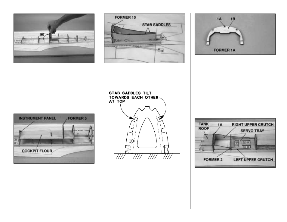
4. Starting at the rear with former 10, glue the
die-cut and laser-cut 1/8" [3.2mm] balsa formers 6
through 10 and the die-cut 1/8" [3.2mm] plywood
formers 3 and 4 between the main stringers where
shown on the plan. Use a small square to hold the
formers perpendicular to the building board as you
glue them.
❏
5. Add the die-cut 3/32" [2.4mm] balsa cockpit
floor, the die-cut 1/8" [3.2mm] plywood instrument
panel and former 5, making sure they are
perpendicular to the cockpit floor as you glue them.
Note: The partially die-cut lines on the cockpit
floor indicate where to remove that portion of the
cockpit floor to accommodate the scale Top Flite
Spitfire Cockpit Interior kit. Do not remove that part
of the cockpit floor until instructed to do so.
❏
6. Glue the die-cut 1/8" [3.2mm] plywood tail
wedge between the main stringers where shown
near the aft end of the fuse plan. Glue both die-cut
1/8" [3.2mm] plywood stab saddles to the main
stringers, the tail wedge and former 10 as shown
in the sketch.
❏
7. Glue the die-cut 1/8" [3.2mm] plywood
former 1B to the back of 1A. From now on this
assembly will be referred to as former 1A.
❏
8. Glue former 1A to the front of the main
stringers, using a square to keep it perpendicular
to your building board (you can see 1A in the
following photo).
❏
9. Join the die-cut 1/8" [3.2mm] plywood right
upper crutch (RUC), left upper crutch (LUC),
servo tray, former 2 and the tank roof (TR). Hold
the parts in alignment and glue them together.
Note: Until you join the bottom crutches to the
assembly, the right and left upper crutches
float
between the main stringers, except where they are
glued to former 1A and former 2.
- 33 -