Top Flite TOPA0140 User Manual
Page 47
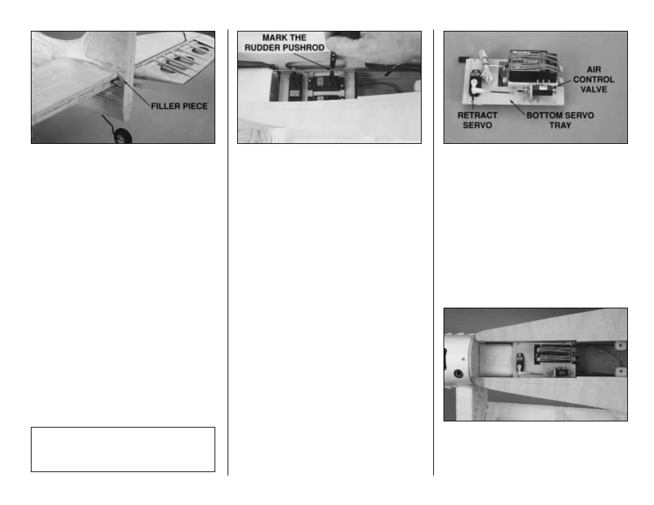
Refer to this photo for steps 8 through 11.
❏
8. If you have the elevators temporarily
attached to the stab, remove them for now. Cut
two
filler pieces from leftover 3/32" [2.4mm] balsa
to fit between the fin sheeting and the fuse
sheeting behind the stab TE on both sides of the
fuse. Do not glue them in yet.
❏
9. Cut a small, round
notch in the front edge of
both filler pieces to accommodate the elevator
joiner wire.
❏
10. Roughen the elevator joiner wire with
sandpaper so glue will stick.
❏
11. Insert the elevator joiner wire into the fuse
and glue the filler pieces in place. Be careful not to
get glue on the elevator joiner wire so that it is free
to pivot. Blend the filler pieces to the fuse with a little
filler if needed and sand to shape.
INSTALL THE RADIO
❏
1. Center the rudder and tail wheel. Use a felt
tip pen to mark the rudder pushrod where it
crosses the holes in the rudder servo arm.
❏
2. Make a 90-degree bend in the pushrod at the
mark you made. Snap a nylon Faslink onto the
wire and cut the wire so approximately 1/16"
[1mm] protrudes from the Faslink.
❏
3. Enlarge the holes in the rudder servo arm
with a #48 [1.90mm] (or 5/64") drill or a hobby
knife. Connect the pushrod to the servo arm with
the Faslink.
❏
4. Connect the elevator pushrod to the elevator
servo the same way.
❏
5. Study the plans and the following photos to
decide how you will mount your receiver, battery
pack, servo for the retract air control valve and the
air control valve itself. We’ve included a removable
bottom servo tray for this purpose. Mount your
receiver, retract servo and air control valve to the
bottom servo tray, or fashion your own mounting
system for these items.
Note: If you plan to install the Top Flite Spitfire
Scale Cockpit Interior kit, an alternate location to
mount your receiver would be on the cockpit floor
shown on page 48. Make certain the cockpit floor
is securely glued into the fuselage if this is where
you decide to mount your receiver.
❏
6. Connect the retract servo to the air control
valve with the hardware of your choice. We used a
2-56 threaded rod with a clevis on one end and a
ball link on the other end.
❏
7. Cut bottom servo tray rails from the 3/16" x
1/4" [4.8 x 6.4mm] basswood stick and glue them
to the lower crutches as shown on the plan. Plan
your installation carefully and test fit the bottom
servo tray in the fuselage before you glue the rails
in place. Make sure you position the rails so they
do not interfere with the other servos.
❏
8. Drill four 1/16" [1.60mm] holes through the
bottom servo tray and the rails. Enlarge the holes
in the bottom servo tray only with a 3/32" [2.40mm]
drill bit and temporarily mount the bottom servo
tray to the rails with four #2 x 3/8" [9.5mm] screws.
Some modelers prefer to install the radio after
they cover the model. If this is your decision, skip
to
Prepare the model for covering on page 49,
then return to this section when you’re done.
- 47 -