Top Flite TOPA0140 User Manual
Page 22
FIT THE LANDING GEAR
❏
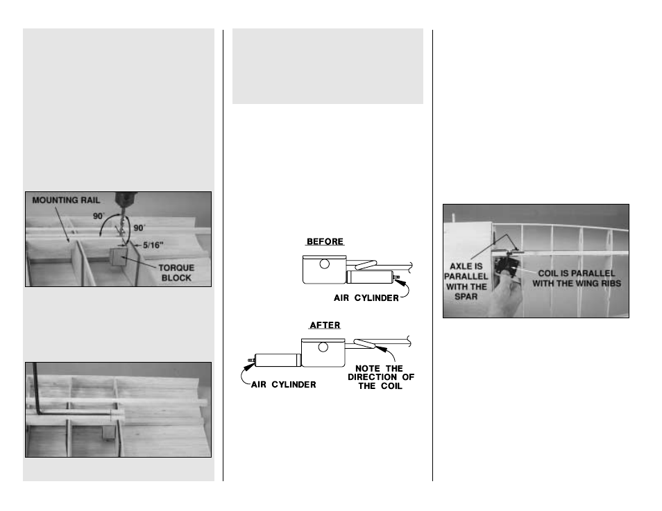
1. Use 30-minute epoxy to glue a 1/2" x 3/4" x
6" [12.7 x 19.1 x 152mm] grooved basswood fixed
gear mounting rail and a 5/8" x 3/4" x 1" [15.9 x
19.1 x 25.4mm] maple torque block to each other
and ribs 4, 5 and 6 in both wing panels as shown
on the plan (
see the following photo). Use a
C-clamp to hold the torque block to the ply doubler
on rib 6 until the epoxy is fully cured.
(Disregard the wing sheeting in these photos.)
❏
2. Mark the bottom of the mounting rails 5/16"
[8mm] from the edge of the ply doubler on rib 6.
Drill a 3/16" [4.70mm] hole through the landing
gear rails and the torque blocks at the mark. As
you drill, make sure you hold your drill at a 90
degree angle to the landing gear rail.
❏
3. Chamfer the inside
edge of the hole in the
landing gear rail to accommodate the bend of the
landing gear. This will allow it to fully
seat in the
groove. Test fit the bent 3/16" [4.8mm] wire
landing gear in the landing gear rail. Make
adjustments where necessary for a good fit.
That’s all for now for the fixed gear. Skip to
Prepare the outer panels for sheeting on page 23.
Perform steps 4 through 13 only if you are
installing retracts.
Our prototype Spitfire uses and this instruction
manual shows how to install, Robart #605 Heavy
Duty (3/16" [4.8mm] wire) 90-degree pneumatic
retracts. Other units may work, but it is up to you
to make any modifications necessary.
❏
4. Disassemble your retracts and mount the air
cylinder so it comes out the other end. Switch the
right and left landing gear wires so the strut will be
below the coil, giving the wheel more room in the
wheel well.
Start with the left wing panel so your progress
matches the photos.
❏ ❏
5. For now, cut the landing gear wire to a total
length of 6" [150mm] (from end to end)—this will be
slightly too long but you can
fine-tune the length
later. A cut-off wheel on a rotary tool works best for
cutting the landing gear wire. Don’t forget your
safety glasses! Bend your landing gear wires
forward until they match the drawing shown on the
wing plan.
❏ ❏
6. Place your retract on the left landing gear
rail in the wing. Position the landing gear wire so
the
coil is parallel with the wing ribs when the
landing gear is extended (see the following photo).
Tighten the set screw to lock the landing gear wire
in this position.
❏ ❏
7. Place a 3/16" [4.8mm] axle on your
landing gear wire 5-3/16" [132mm] from the retract
pivot point. Position the axle so it is parallel with
the main spar and tighten the set screw to lock the
axle in position.
❏ ❏
8. Remove the die-cut piece from rib 6 to
accommodate the wheel when you test fit the
landing gear.
❏ ❏
9. Cut out rib 5 as necessary to clear the
landing gear wire when you retract it into the wing.
Use a rotary tool and a sanding drum if you
have one.
Perform steps 1, 2 and 3 only if you are
building fixed landing gear.
- 22 -