Toa SR-PB5 User Manual
Page 7
7
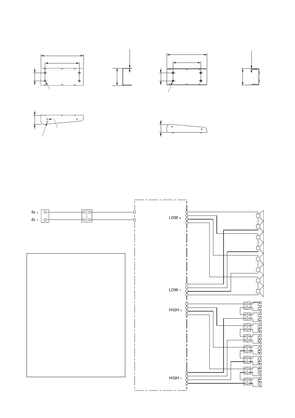
5. INTERNAL WIRING DIAGRAM AND INPUT OVER-VOLTAGE
PROTECTION CIRCUITRY
The internal wiring from the input terminal to the speaker units is as shown below.
4.2. SR-PB5 Wall Pan Bracket (Optional)
4.2.1. Pan bracket A (Quantity: 2)
4.2.2. Pan bracket B (Quantity: 2)
(1.97)
50
265 (10.43)
213 (8.39)
4 - ø12 (0.47)
For anchor bolt (Refer to p. 12 and p. 19.)
(4.22)
107.2
2.6 (0.1)
(2.24)
57
Unit: mm (inches)
Horizontal angle adjustment hole (for 5°)
Horizontal angle adjustment hole (for 10°)
(1.97)
50
(1.97)
50
4 - M8
Unit: mm (inches)
249 (9.8)
173 (6.81)
(4)
101.5
Use this hole to join the bracket supplied
with the SR-T5. (Refer to p. 18.)
2.6 (0.1)
Input
terminal
Interlocked connectors for
the matching transformer
Network pc board
About the input over-voltage
protection circuitry
The speaker system has a built-in input
over-voltage protection circuitry for the
tweeters. If an excessive input signal is
applied to the speaker, the protection
circuitry works to cut off the signal input
to the tweeters.
A sudden drop of the volume level in
high frequencies during speaker
operation indicates that the over-
voltage protection circuitry has been
activated. In such a case, reduce the
amplifier volume and wait.
The protection circuitry is automatically
reset in approximately 10 seconds.
After the situation returns to normal, set
the volume at a level lower than before.