Chapter 1 - introduction, Tilt gyro compensation is now available as an, Contrast is now adjustable with the +/- keys – TeeJet CenterLine 230BP User Manual
Page 4
CenterLine 230BP
020-020-UK R0
3
Tilt Gyro compensation is now available as an
•
upgrade to the CenterLine 230 BP. For part
numbers and pricing, please consult your re-
gional TeeJet Technologies representative.
The upgrade includes the support of Field-
•
Pilot Assisted Steering. Connection to the
SCM is now via CAN. Existing FieldPi-
lot 220 customers upgrading to FieldPilot
230 must arrange to exchange their SCM.
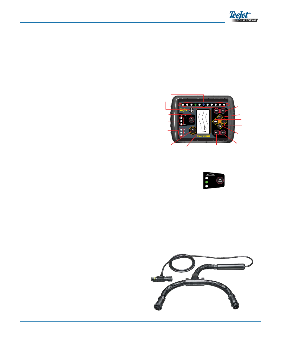
NOTE: The swath status bar is only active if a
smartcable is installed.
SMART CABLE - The Smart Cable is the link
between the CL230BP, the existing rate controller,
and the boom section valves. It allows the CL230BP
to control the boom sections automatically and is
necessary to allow for Automatic Boom Section
Control. For the user guide covering the additional
features with an added SmartCable, please
refer to CL230BP User Guide 020-034-UK R3.
ALL ON
AUTO
MAN
CHAPTER 1 - INTRODUCTION
This User Guide provides information for software
version 1.07.
The CenterLine 230BP (CL230BP) software 1.07
provides the following enhancements to the system:
Applied area now includes only the area under
•
the active boom sections and acre counters will
accurately represent applied area. Prior calcu-
lations counted all area under the entire boom,
regardless of whether individual sections were
on or off.
Unapplied area is now considered “untreated”
•
and can be treated at a later time.
Boundary area is calculated and displayed as
•
a result of a headland perimeter pass in head-
land circuit mode. This value is held in memory
through the next power cycle and is erased when
the user chooses to clear the memory and begin
application of a new area.
When a fi eld boundary is created in headland cir-
•
cuit mode, a “No Spray” zone is created outside
of that fi eld boundary. This boundary and “No
Spray” zone is held in memory through the next
power cycle.
Area information and as-applied data are now
•
updated and saved with greater frequency.
Drive Sensitivity (LED spacing on the lightbar)
•
can now be changed in the system Setup menu.
A section width of “0.0” can now be entered.
•
Contrast is now adjustable with the +/- keys
•
during the startup splash screen. Once GPS
is attained, the +/- revert back to adjustment of
screen Brightness.
A system setting for “GPS Source” allowing a
•
devoted external source has been added. The
default GPS source is the internal GPS receiver.
DGPS LED activation will now cycle through a 2
•
minute delay for the purpose of stabilizing DGPS
performance. It is recommended guidance mode
operation begin after the DGPS LED is active.
ESC
GPS
GPS
DGPS
ALL ON
AUTO
MAN
Power
Increase/Decrease
Swath Status Lights
GPS Status Lights
Change Page
Setup Mode
Escape
Enter
Display
Return to Point
Mark A/B
Line
Guidance Mode
Lightbar
Swath Status
(Selects Mode)