Microprocessor controls and indicators – Sonics X-Press Integrated Welder User Manual
Page 14
• • • • • • • • • • • • • • • • • • • • • • • • • • • • • • • • • • • • • • • • • • • • • • • • • • • • • • • • • • • • • • • • • • • • • • • • • • • • • • • • • • • • • • • • • • • • • • • • • • • • • • • • • • • •
I N S T R U C T I O N M A N U A L • M O D E L X - P R E S S
13
O P E R A T I N G P R O C E D U R E S
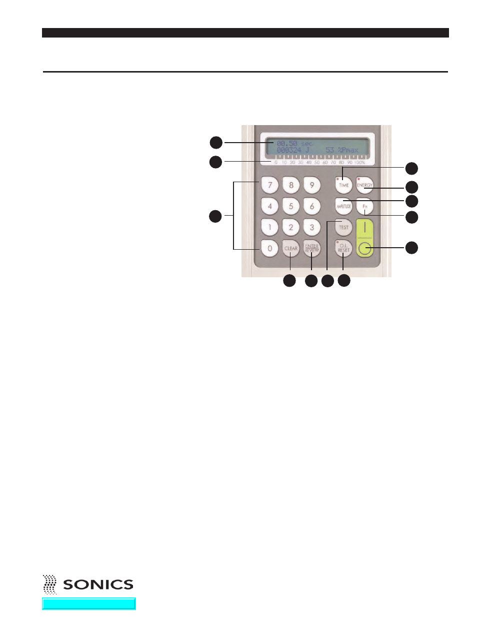
MICROPROCESSOR CONTROLS AND INDICATORS
Located at the front of the press are the following controls and indicators:
1. ON/OFF keys which turn the unit on and off.
2. LCD SCREEN which displays various settings, parameters and prompts
as detailed in the following pages. In addition, during the weld process it
displays a load meter indicator showing the power level of ultrasonics that
is being delivered to the welding press (see #3 below).
3. LOAD METER SCALE from 0 to 100% which (in conjunction with
vertical line indicators on LCD display) shows the running power (bar
graph at bottom of display) and peak power (single vertical line at top of
display) during the weld. Peak power is reported as %Pmax after the cycle
4. TIME key which allows selection and display of time settings and permits
adjustment of time duration in .01 second increments (from 00.00 to 99.99
seconds) for six time parameters as follows:
a. Weld time
b. Hold Time
c. Delay time
d. Afterburst Time
e. Time Limit Low
f. Time Limit High
For a complete explanation of these parameters, refer to page 18.
1
2
3
4
5
7
6
8
9
10
3
11
4
12
Go To Top Of Document