Slant fin corp – Slant/Fin CHS-399 User Manual
Page 42
Slant Fin Corp.
│ Installation and Operation Instructions
CHS Series
42
Boiler System Plumbing
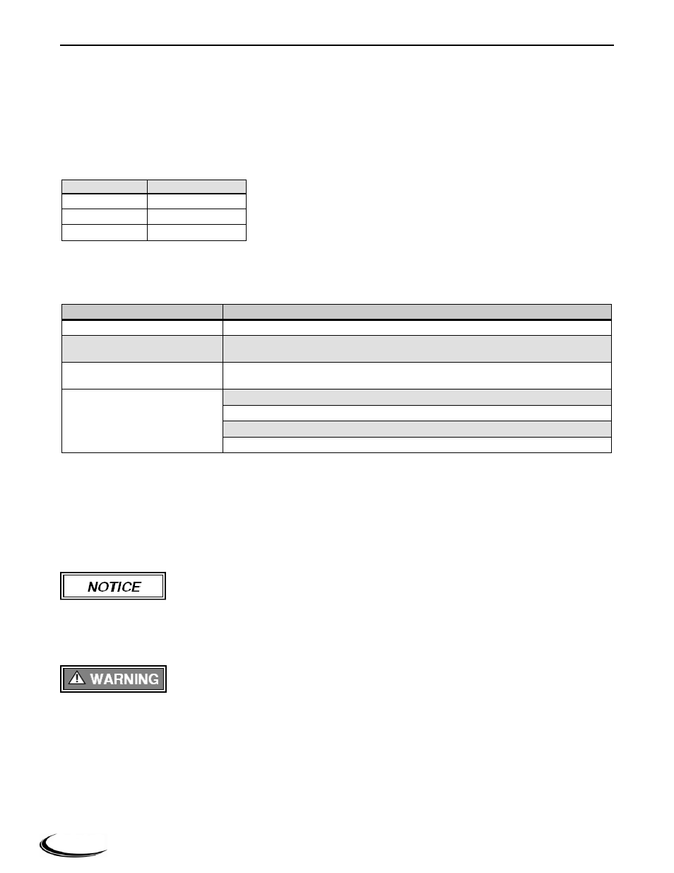
The CHS boiler uses a low mass heat exchanger that requires a minimum rate of forced water circulation any
time the burner is operating (See Table 10-2 for minimum flow rate requirements). To ensure the minimum flow
rate is attained, Slant/Fin strongly recommends installing the boiler in a “Primary/Secondary” plumbing
configuration utilizing “Closely Spaced Tees” or a “Low Loss Header” to de-couple the Boiler-Primary loop
from the System-Secondary loop(s). See the examples of Primary/Secondary Loop configurations in Figures 10-
5 and 10-6.
Table 10-2 Minimum Flow Rate Requirements
Model
Flow (US gpm)
CHS 85-110
3.5
CHS 155-250
7.5
CHS 300-399
12
System Components – As a minimum, a properly installed system will include the following major components
identified in Table 10-3.
Table 10-3 System Major Component Checklist
Factory Supplied
Components
Field Supplied Components
Pressure Relief Valve
Boiler Loop Circulator (Pump B in Figure 10-5 or Pump C in Figure 10-6)
Pressure Gauge
DHW Loop Circulator (Pump A in Figure 10-5 and Figure 10-6, for applications
utilizing and Indirect Fired Water Heater)
Auto Air Vent
Central Heat (CH) Loop Circulator(s)
(CH Circulator - Pump C in Figure 10-5; Zone Circulators in Figure 10-6)
Central Air Removal Devices (i.e. Micro Bubbler or Air-Scoop)
Pressure Regulating “Fill Valve”
Backflow Preventer
Expansion Tank
Circulating Pumps – CHS boilers are equipped with three 120VAC pump outputs:
1. PUMP A
“DHW Pump” - operates during a Domestic Hot Water demand (DHW).
2. PUMP B
“Boiler Pump” - operates during any demand.
3. PUMP C
“CH Pump”
- operates during a Central Heat/Thermostat demand (THERMOSTAT).
Ensure pumps are oriented as per the manufacturers’ instructions. Wiring of these circulators will depend on the
system configuration selected; see Figures 10-5 and 10-6. For further wiring details see Section 11.0.
Circulators responsible for forcing the water flow through the boiler must be sized
according to Table 10-4. Pump recommendations are based on a Primary/Secondary
plumbing configuration (see Figures 10-5 and 10-6) using the listed pipe size in the Boiler-Primary Loop, with
up to 50 equivalent feet of pipe length. The installer is responsible for sizing the boiler circulator(s) and piping
for applications using non Primary/Secondary plumbing; Figure 10-4 provides Head Loss curves for this
purpose.
Failure to ensure the minimum water flow rate through the boiler when the burner is
operating will result in “short-cycling”, reduced performance and operating efficiency,
and may also cause overheating and premature failure which will void the warranty. Failure to follow
instructions may result in fire, property damage, serious injury or death.