SilentKnight IP Communicator User Manual
Page 7
IP Communicator Series Installation Document — P/N 53109:I 4/26/2010
7
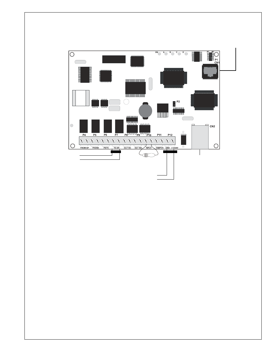
Wiring the IPDACT Series Within the Fire Alarm Control Panel Enclosure
Figure 5 and Figure 6 detail the connections that must be made between the IPDACT Series and the FACP.
RJ45 Connector for connection to RS232 serial port.
Use a Serial to USB converter if the computer does not have an RS232 port.
(FOR PROGRAMMING USE ONLY)
Supplied Phone Cable
Supplied Phone Cable
(factory
installed)
Ferrite*
Ferrite*
(minimum wire
gauge 22-14 Awg)
(Note the the male plug connectors on the other end of the Supplied Phone
Cable, plug into the Primary and Secondary Phone Jacks on the FACP DACT.)
1K
Ω ELR
From FACP Nonresettable 24VDC (-)
From FACP Nonresettable 24VDC (+)
(minimum wire gauge 18-14 Awg)
RJ45 Connector for connection to
Ethernet/Internet (minimum wire
gauge 24-22 Awg)
* Refer to Figure 7 for Ferrite Bead Installation.
The smaller ferrite bead is used on the “TO AP”
connection.
The larger ferrite bead is used on the “24VDC”
connection.
Figure 5 IPDACT Wiring
ip
da
c
tbr
d.
wmf
- 5104 Digital Alarm Communicator Transmitter 6 Zone (48 pages)
- 5128 Digital Alarm Communicator Transmitter (42 pages)
- 5217 10-Zone Expander for 5208 (2 pages)
- 5220 Direct Connect Module (2 pages)
- 5235 Remote Annunciator for 5208 (2 pages)
- 5280 Status Display Module for 5208 (2 pages)
- 5495 6A Distributed Power Module (52 pages)
- 5496 6A Intelligent Remote Power Supply (38 pages)
- 5499 9A Distributed Power Module (56 pages)
- 5600 (114 pages)
- 5660 Silent Knight Software Suite (28 pages)
- 5670 IntelliKnight Facility Management Software (24 pages)
- 5700 (180 pages)
- 5808 (180 pages)
- 5815RMK Remote Mounting Kit (2 pages)
- 5815XL Signal Circuit Expander (2 pages)
- 5820XL-EVS (236 pages)
- 5824 Serial/Parallel Module (2 pages)
- 5860/5860R Remote Annunciator (2 pages)
- 5865-3/5865-4 Remote LED Annunciator (2 pages)
- 5880 LED Driver Module (2 pages)
- 5883 Relay Interface Board (4 pages)
- 5895XL 6A Intelligent Remote Power Supply (56 pages)
- B200S Intelligent Sounder Base with CO Support (4 pages)
- B200S-LF - Low Frequency Intelligent Sounder Base (4 pages)
- B200SR Sounder Base (4 pages)
- B200SR-LF Low Frequency Intelligent Sounder Base (4 pages)
- B210LP 6 Mounting Base (2 pages)
- B224BI 6 Mounting Base w/Built-in Isolator (2 pages)
- B224RB 6 Mounting Base w/Built-in Relay (4 pages)
- B501 4 Mounting Base (2 pages)
- Central Station Monitoring List (1 page)
- Document Revision History (4 pages)
- EVS (74 pages)
- EVS-CE4 (2 pages)
- EVS-RVM (2 pages)
- EVS-VCM (2 pages)
- FFT (1 page)
- FFT-24 (2 pages)
- FFT-24 Installation (1 page)
- FFT-FPJ (1 page)
- FFT-HSC (1 page)
- FFT-STSS and FFT-STSR (2 pages)
- HFS-D (4 pages)
- HFS-MM (1 page)