SilentKnight IP Communicator User Manual
Page 11
IP Communicator Series Installation Document — P/N 53109:I 4/26/2010
11
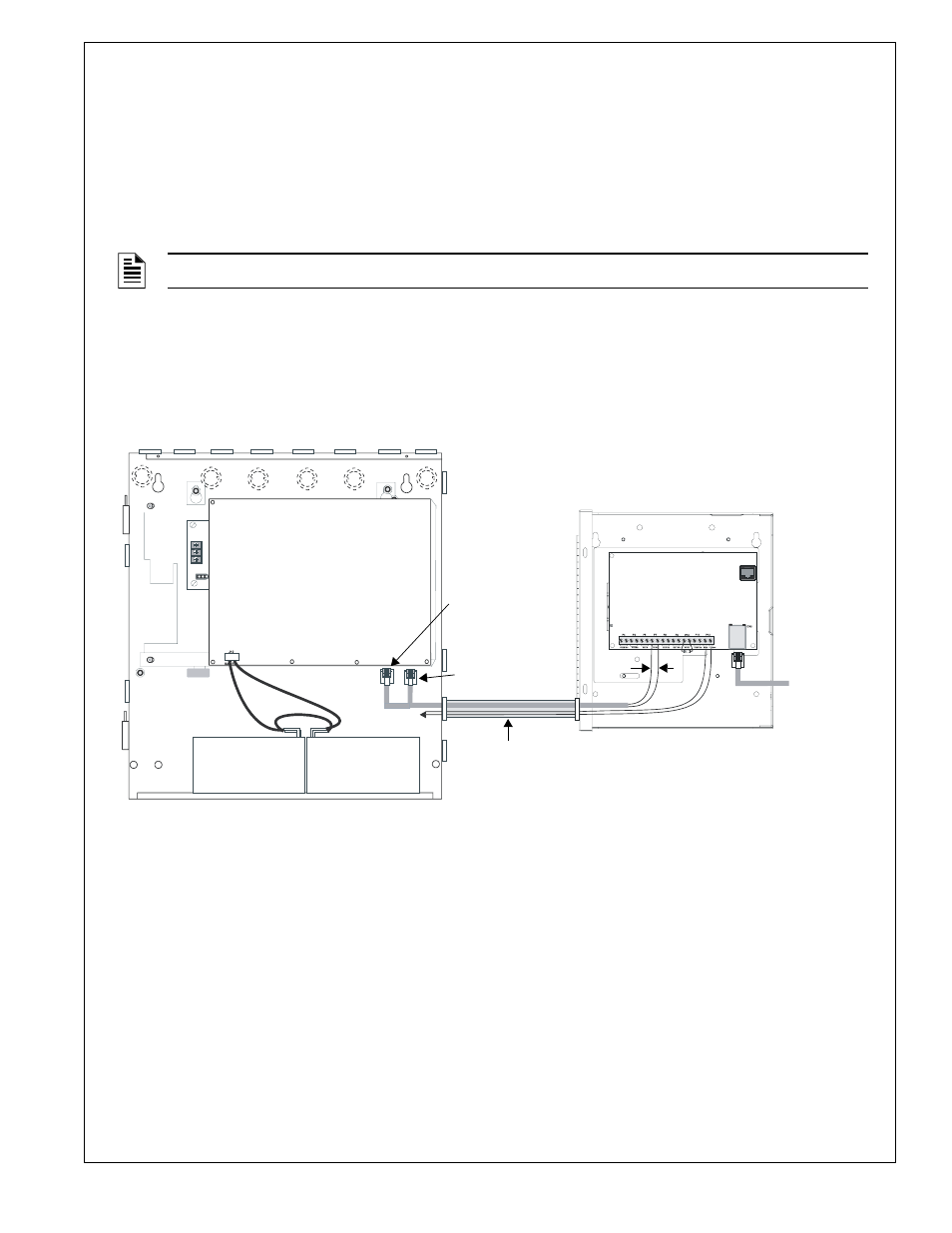
Wiring the IP Communicator to the Fire Alarm Control Panel (refer to Figures 10 and 11)
1.
Remove all power (AC and DC) from the FACP before installing any wires.
2.
All wiring between the FACP and IPDACT Series must be in metal conduit which is no more than 6” in length. (The
IPDACT Series must be installed within the same room as the FACP).
3.
Connect one end of the supplied phone line cable to the Primary and Secondary Phone Line connectors on the FACP
by inserting the male plugs into the RJ45 connectors.
4.
Wire the other end of the supplied phone line cable to the TO AP terminals as illustrated in Figures 5, 6, 10 and 11 of
this document.
5.
Connect Nonresettable 24 VDC power from the FACP to the power terminals on the IPDACT Series.
6.
Connect the RJ45 connector on the IPDACT Series to an Ethernet/Internet connector.
7.
Refer to the appropriate FACP manual for power specifications and wiring details and to Figures 5 and 6 in this
document for IPDACT connection details.
8.
Reapply all power (AC and DC) which was removed in step 1.
NOTE:
Tip & Ring wire connections for TO AP terminal are interchangeable.
FACP
Main Circuit Board
Primary
Phone Line
†
Secondary
Phone Line
†
metal conduit (6” max. when
using the supplied phone
cables). Longer distances (up
to 20’ within the same room)
is acceptable when
supplemental phone cables
are used.
*FACP Power Supply requirements- refer to the table
on page 1 for each version of the IPDACT Series.
FACP Backbox
IPDACT
24 VDC*
RJ45
Ethernet/
Internet
Connection
Figure 10 IPDACT Connections to FACP
to AP
to AP
†
Refer to Tables 1 and 2 for applications where the phone lines
must be connected to an installed UDACT/DACT-E3.
IPENC
Enclosure
IP
-E
NCFtoFA
C
P
2a
.wmf