SilentKnight IP Communicator User Manual
Page 13
IP Communicator Series Installation Document — P/N 53109:I 4/26/2010
13
3.
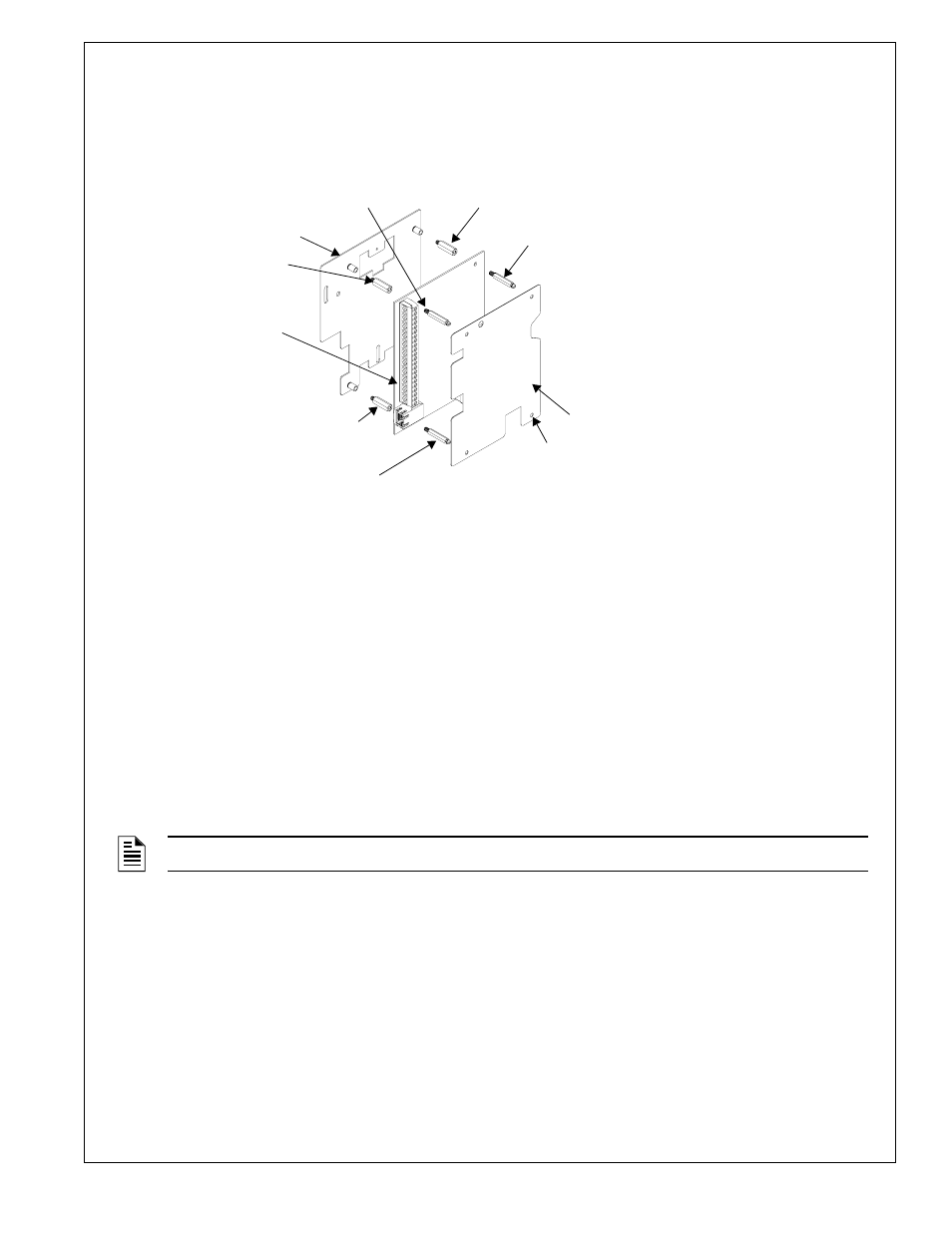
Attach the four supplied 0.75” M/F standoffs to the IPBRKT as shown in Figure 13.
4.
Then, secure the IPDACT Series Module to the IPBRKT using the four supplied M/M standoffs (three for IPDACT-2
and IPDACT-2UD).
5.
Wire the IPDACT Series as described in the following sections of this document.
6.
Attach the polycarbonate cover with label by pressing it onto the four standoffs installed in step 4.
Wiring the IPDACT Series to the HP300ULX Power Supply and FACP
Note: If a 411UD is also installed, refer to for details on wiring both units.
Refer to Figure 14 on page 14 (IPDACT) or Figure 15 on page 15 (IPDACT-2/UD) for an illustration of the following
wiring details.
1.
Connect the AC power terminals of the FACP and HP300ULX Power Supply to the same AC power main feed. A
loss of AC power will cause the FACP to generate an AC Power Loss indication which will be recognized as an AC
power loss for both panels.
2.
The phone lines between the FACP and IPDACT Series, which is mounted in the HP300ULX backbox, must be in
conduit. (The IPDACT Series must be installed in the same room as the FACP).
3.
Connect one end of the supplied phone line cable to the Primary and Secondary Phone Line connectors on the FACP
by inserting the male plugs into the RJ45 connectors.
4.
Wire the other end of the supplied phone line cable to the TO AP terminals of the IPDACT Series as illustrated in
Figure 14 (IPDACT) or Figure 15 (IPDACT-2/UD) on the following pages and in Figures 5 or 6 of this document.
5.
Connect Nonresettable 24 VDC power from the HP300ULX to the power terminals on the IPDACT Series as
illustrated in Figure 14 (IPDACT) or Figure 15 (IPDACT-2/UD).
6.
Connect one wire from the Battery Fail NO (Normally Open) contact of the HP300ULX to one of the Input
terminals on the IPDACT Series and a second wire from the Battery Fail C (Common) contact of the HP300ULX to
the other Input terminal on the IPDACT Series. This will allow the IPDACT Series auxiliary trouble input terminals
to monitor for an HP300ULX battery failure.
7.
Install a 1K
Ω ELR across the Battery Fail NO (Normally Open) contact and the C (Common) contact to allow the
IPDACT Series to supervise the wiring.
8.
Connect the RJ45 connector on the IPDACT Series to an Ethernet/Internet connector.
9.
Refer to the appropriate FACP manual for power specifications and wiring details and to Figures 5 or 6 in this
document for IPDACT connection details.
NOTE:
Tip & Ring wire connections for TO AP terminal are interchangeable.
M/F standoff (not used for IPDACT-2 or IPDACT-2UD)
standoff (not used for IPDACT-2 or IPDACT-2UD)
standoff
standoff
IPDACT Module
IPBRKT bracket
polycarbonate cover with label
Figure 13 IPDACT Series Mounting in HP300ULX
HP
30
0
U
LX
in
st
a
ll3
.wmf
M/F standoff
M/F standoff
standoff