Contactor 7, Fuse 7, Convenience outlet 7 – Reznor HRPD Parts Manuals User Manual
Page 7: Potentiometer 7, Air proving switch 7, Emperature controller 7, Erminal blocks 7, Blower cabinet electrical component location
Form P-RG/RP/RBL, P/N 263984R4, Page 7
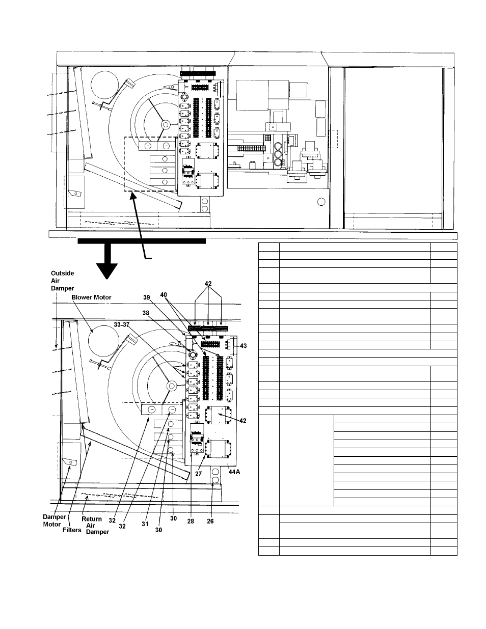
Blower Cabinet Electrical Component Location
("B" Cabinet is illustrated; control locations are the
same in the larger capacity "BL" Cabinets)
Optional Downturn
Plenum Cabinet
Code Description
P/N
25 Fuse Holder (Fuse, see page 9)
60241
26 Convenience Outlet
96912
27A Blower Motor Contactor - 24V Coil
(replaces P/N 93661 and P/N 119625)
216386
27B Blower Motor Starters - see P/N's on pages 27-30.
28 Temperature Controller (Options AG41, AG42)
197204
29 High Ambient Limit Control (Opt BN2)
126170
30 Outside Air or Return Air Controller
(or
P/N 197204, J/C A19ABC-24)
126170
31 Mixed Air Controller
16109
32 Potentiometer
16110
33 Starter Relay (replaces 105803)
110656
34 Summer Winter Relay (Option BF2) - See P/N's on page 10.
35 RBM Relay (BG Options) - See P/N's on page 10.
37 2-Speed Motor Speed Selector Relay - See
illustration in CODE 33, page 10.
110656
38 Auto Reset Reverse Flow Limit
103323
39 Return Air Firestat (Option BD3); See Code 4, pg 8. 42782
40 Low Voltage Terminal Blocks
144972
41 Low Voltage Terminal Block Adapters
144973
42A
and
42B
Control and
Damper
Transformers
(See Chart on
page 5.)
115V to 24V, 20VA
103054
115 to 24V, 40VA
103055
208/230 to 24V, 40VA
103497
460 to 24V, 40VA
103498
208 to 24V, 200VA
38634
230/460/575 to 24V, 200VA
39095
230/460/575 to 115V, 300VA
105202
208 to 115V, 500VA
86998
230/460 to 115V, 500VA
86997
575 to 115V, 500VA
112641
575 to 115V, 750VA
112642
43 Air Proving Switch
112107
44A
Blower Cabinet Electrical Box - std left side controls
100092
Blower Cabinet Electricall Box - optional right side
controls
95486
44B Electrical Box Cover
100095
44C Electrical Box Top
196648
Reference NOTE: Except where a page number is listed,
see pages 8-10 for illustrations and additional information
about electrical components.
Building Management Control NOTE: If equipped with Option D1-D4 for DDC interface to the building's
computerized environmental control system, the dotted line (top illustration) indicates the location of the electrical
box that houses the specially programmed Johnson Control Metasys
®
control unit. Box Cover is
P/N 171739. Other
components are listed on page 11.
See Note at the bottom of
the page about building
management control
option.