Oltage 5, Relay chart 5, Ransformer 5 – Reznor HRPD Parts Manuals User Manual
Page 5: Line voltage application to package configuration
Form P-RG/RP/RBL, P/N 263984R4, Page 5
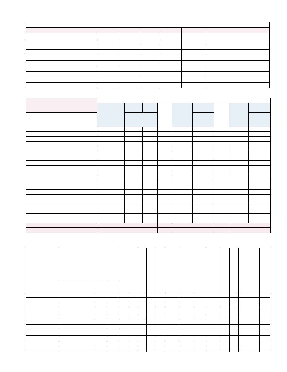
Line Voltage Application to Package Configuration
Line Voltage to Furnace or Packaged System
Unit Voltage
115
208
230
460
575
Comments
RG Control Volts In/Out/VA
115/24/20 208/24/20 230/24/20 460/24/20
N/A
Furnace only
RGB Motor Voltage
115
208
230
460
575
RGB Controls Volts In/Out/VA
115/24/40 208/24/40 230/24/40 460/24/40 575/24/200
RP Control Volts In/Out/VA
115/24/40 208/24/40 230/24/40 460/24/40
N/A
Furnace only
HRPD Control Volts In/Out/VA
115/24/40 208/24/40 230/24/40 460/24/40
N/A
Furnace only
RPB Motor Voltage
115
208
230
460
575
RPB Controls Volts In/Out/VA
115/24/40 208/24/40 230/24/40 460/24/40 115/24/40 575 to 115V / 300VA Transformer
RPBL/RGBL/PGBL 400
115
208
230
460
115
575 to 115V / 300VA Transformer
RPBL/RGBL 500-800; PGBL 800
115
208
230
460
115
575 to 115V / 500VA Transformer
RPBL/RGBL 1050-1200; PGBL 1200
115
208
230
460
115
575 to 115V / 750VA Transformer
Quick Reference Charts (NOTE: Consult wiring diagram to verify relays and transformers.)
Transformer Chart
Relay Chart
Relay P/N
211411 Relay
with Socket
211415 begin-
ning 9/2011
103317* 98118*
110656
259780
beginning
02/2010
259518* or
46233*
209164
262337
beginning
12/2010
206146*
Where Used
Order Replace-
ment Kit 263527
Order Re-
placement
Kit 259521
Order Re-
placement
Kit 262375
Freezestat Relay
X
X
Starter Relay
X
Summer/Winter Relay (Option BF2)
X
X
SPST Relay (BG Option)
X
X
SPDT Relay (BG Option)
X
X
Illinois School Code Controls (Option
BM12)
X
X
Two-Speed Motor Relay
X
Two-Speed Motor Speed Relay
X
IRI Gas Controls (Option BM13)
X(4)
Discharge Damper Relays
X (2)
X(2)
Time Delay Relay Venter (RP Series &
PGBL)
X
X
Blower Relay
X
X
DDC Interface Relay (Options D1, D2,
D3, D4)
X (2or3)
Fan/Blower Control (replaced
temperature activated fan control 12/04)
X
Gas Control Options AG39, AG40, AG41,
AG42
X
X
For additional information, see CODE(S):
34, 35
33
12
14
138
On Page
10
10
9
9
15
Transformer
P/N
Transformer
Volts
RG Controls
RP
Controls
RGB(L) Controls
RPB(L)Controls
PGBL
Controls
RBHA/RBA/RBL
Controls
575V Line RPBL/ PGBL400
575V Line RPBL400- 800; PGBL
800/1200
575V Line RPBL
1050-1200
IRI Manifold
FM Manifold
Used in Option D1-4 (DDC from building's environmental control system)
Discharge Damper
In
Out VA
103054
115
24
20
X
103055
115
24
40
X
X
X
X
X
X
103497
208-230
24
40
X
X
X
103498
480
24
40
X
X
X
38634
115
24 200
X
39095
208-230-460-575 24 200
X
X
X
X
105202
208-230-460-575 115 300
X
X
X
X
X
86998
208
115 500
X
86997
230-460
115 500
X
112641
575
115 500
X
112642
575
115 750
X
* These P/N's are for reference only; the parts are no longer available.