Air pressure switch 6, Stage controller 6, Ductstat 6 – Reznor HRPD Parts Manuals User Manual
Page 6: Electrical component locations 6, Fan control 6, Dirty filter pressure switch 6, Auto reset 6, Gas pressure switch 6, Ignition controller 6, Limit control 6
Form P-RG/RP/RBL, P/N 263984R4, Page 6
Maxitrol Amplifier
See Form P-VALVES
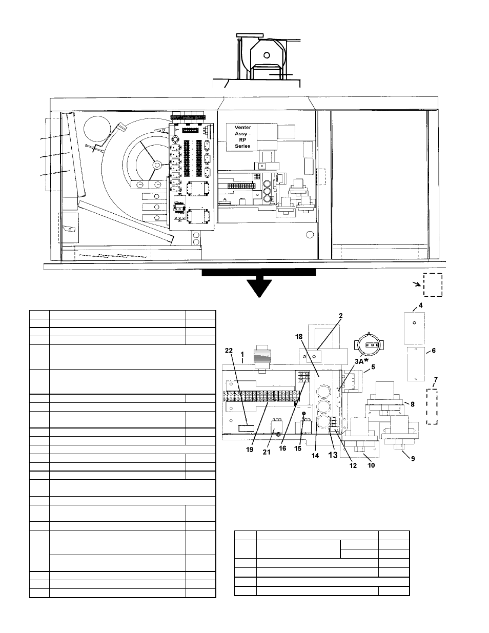
Furnace Electrical Component Locations
("B" Cabinet is illustrated; control locations are
the same in the larger capacity "BL" Cabinets)
Code Description
P/N
18
Heat Shield (on units
mfgd prior to 12/04)
U.S.
10188
Canada
63818
19
Low Voltage Terminal Blocks
144972
20
Low Voltage Terminal Block Adapter
144973
21
Freezestat Relay - See P/N's on page 9.
22
Dirty Filter Pressure Switch
105507
NOTE: See pages 8 - 10 for illustrations
and additional information about the
furnace electrical components listed below.
Venter assembly and
combustion air switch on
indoor Model PGBL is on top
of the unit.
Optional Downturn
Plenum Cabinet
*Code 3A - Beginning with units manufactured 2/99, the
pressure switch on RP Series units is mounted inside the
electrical box. Prior to 2/99, the pressure switch is mounted
on the wall of the electrical compartment above the electrical
box. See page 8 for replacement information.
3B
Code Description
P/N
1A Electrical Box
100108
1B Electrical Box Cover
100109
2
Freezestat, Auto Reset (Option BE2)
126170
3A*
Combustion Air Pressure Switch -- Replacement switch
depends on the date of manufacture and original
equipment; see P/N's on page 8.
3B
Combustion Air Pressure Switch (PGBL, top of page)
-- Replacement switch depends on the date of manu-
facture and original equipment; see P/N's on page 8.
4
Discharge Air Firestat (Option BD2)
42782
5
Ignition Controller - See P/N's on page 8.
6
Discharge Air Sensor (modulating gas
controls)
48041
7A 2-Stage Controller (for Option AG3)
41700
7B 2-Stage Ductstat Sensor Holder (AG15-20)
115850
7C Remote Ductstat Modules (AG15-20) - see page 8.
8
Low Gas Pressure Switch, 1-6" w.c.
93849
9
Low Gas Pressure Switch, 6-24" w.c.
149176
10 Main High Gas Pressure Switch (Opt BP2)
93850
11 Gas Pressure Switches in Opt AG39, AG40, AG41, and
AG42 - location not shown; see page 9.
12 Time Delay Relay (RP Series) - See P/N's on page 9.
13A Limit Control RG(B) & RP(B) only (for BL
systems, see page 10)
50417
13C Limit Shield RG(B) & RP(B) only
12229
14
Fan Control - Effective 12/04, a temperature
activated fan control is no longer available.
Order Replacement Kit, P/N 209184.
209184
Fan Control Time Delay Relay (on units mfgd
beginning 12/04; check wiring diagram)
209164
15 Freezestat Time Delay Relay
89661
16 Line Voltage Terminal Blocks
144972
17
Line Voltage Terminal Block Adapter
144973