Control compartment 4, Electrical components 4 – Reznor UDBP Parts Manuals User Manual
Page 4
Form P-UD, P/N 270285R4, Page 4
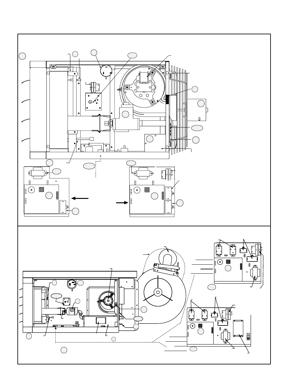
Flame
Sensor
Limit Control
Venter Motor, page 13
Burner
Assy
, pg 14
Gas
Valve
Orifice
Ignitor
Starter or Contactor
(UDBS location), page 7
Electrical Box (UDBS only)
Box Cover
Door Interlock
(UDBS only)
Terminal Board
and Gasket
Disconnect Switch
(UDBS only)
Blower,
page 12
Motor, page 8
Optional Relays
Ignition
Board
Capacitor,
page 8 & 13
Top View -
Model UDBS
Control
Bracket Assy
Control Transformer
Pressure
Switch*
Starter or Contactor
(UDBP location), page 8
Control Transformer
Ignition
Board
Optional
Relays
Top View -
Model UDBP
Control
Bracket Assy
Control bracket assembly is on the bottom of the control compartment.
14
1,2,3
15
9
18
20
19
10A
7
10A
7
5,6
Control Bracket and Gasket only
Capacitor,
page 8 & 13
Optional Belt Guard,
page 18
8
*Prior to 9/03, pressure
switch was on the control
bracket on the bottom of
the control compatment.
UDBP - Location
of pressure switch
prior to 9/03.
UDBS - Location
of pressure switch
prior to 9/03.
16,17
*Pressure Switch
(location all sizes
beginning 9/03)
Venter Motor, page 13 (Size 30-75 illustrated.
Venter motor is in the same location for all
sizes, but appearance is different.)
Fan
Motor
Gas Valve
Transformer
Circuit Board
(DSI Integrated
Control Module)
Optional Fan Motor
Capacitor
High Temperature
Limit Control
Flame Rollout Switch
(Sizes 30-125)
Ignitor
Flame
Sensor
Burner
Assembly , p
age 14
Terminal Board
(24V) & Gasket
Transformer
Circuit Board
(DSI Integrated
Control Module)
Venter
Motor
Capacitor,
page 13.
Control Panel Assy
located on the
Control Compartment
Bottom
Sizes 30-125
Sizes 150-400
Model UDAS has a
collar for combustion
air pipe (not illustrated)
Interlock Door
Switch - UDAS only
Electrical Box - UDAS only
Remove cover to connect supply wires
and access disconnect switch. Always
replace cover.
Disconnect Switch
- UDAS only
4
8
1,2,3
12
16,17
19
20
18
9
10A
13
7
15
10A
13
Fan Motor
Capacitor
Box
Cover
5, 6
Control
Panel Bracket
& Gasket
*Pressure switch location for
all sizes manufactured beginning
9/03. Sizes 30-125 mfgd prior, the
pressure switch was on the com-
partment wall directly above the
high temperature limit. Sizes
150-400 mfgd prior, the pressure
switch was on the control bracket
on the bottom of the compartment.
14
150-400 Pressure switch
location prior to 9/03.
30-125
Pressure
switch
location
prior to 9/03.
7
Control Compartment - Models UDAP and UDAS Sizes 30-400
Electrical Components - Location, Quantity (Quantities other than one are listed in parenthesis.),
and P/N (see page 6 for photos)
Control Compartment - Models UDBP and UDBS Sizes 150-400