Filters, Manifold gas pressure, 1b. blower belts – Reznor DV Operation Manual (for units built before August 2003) User Manual
Page 4: Recommended bearing lubrication schedule in months, Quantity and size of filters by model, Re s, Figure 1 - belt tension, Figure 2 - gas pressure tap locations
Form
O-DV/RDF/ADF, P/N 148385, Page 3
R
E
S
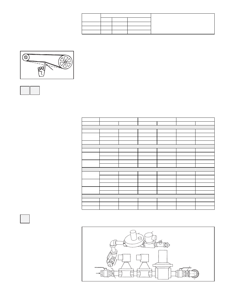
1B. Blower Belts
Check belts for proper tension and wear. Adjust belt tension as needed. Re-
place worn belts.
Proper belt tension is important to the long life of the belt and motor. A loose
belt will cause wear and slippage. Too much tension will cause excessive
motor and blower bearing wear. If adjustment is required, adjust belt tension
by means of the adjusting screw on the motor base until the belt can be de-
pressed 1/2" to 3/4" (FIGURE 1). Tighten the lock nut on the adjusting screw.
Be sure the belt is aligned in the pulleys.
FIGURE 1 - Belt Tension
2. Filters
If the system includes filters, check the filters quarterly. Filters could be either
in an optional filter cabinet (DV/RDF/ADF) or in the optional inlet base (DV).
To access filters in a filter cabinet, remove the filter cabinet door panels. Clean
or replace as needed. If removed, be sure to put blockoff plates in filter rack.
If the filters are in the perimeter of the inlet base of a Model DV; they are two-
inch permanent filters. Remove and clean the filters as needed.
3/4 (19mm)
3. Manifold Gas
Pressure
Semiannually, check the gas pressure to the burner and to the pilot. Measure
both manifold pressure and pilot supply pressure with the blower in opera-
tion. Verify against pressures listed on the rating plate.
Recommended Bearing
Lubrication Schedule in
Months
Bearing Bore Diameter (Inches)
RPM
1/2 to 1 >1 to 1-1/2 >1-1/2 to 1-15/16
to 1000
6
6
6
1001 - 1500
5
5
5
1501 - 2000
5
4
5
NOTE: If unusual environmental conditions
exist (temperatures below 32°F or above
200°F; moisture; or contaminants) more
frequent lubrication is required.
Quantity and Size of
Filters by Model
Type
Thickness
1"
2"
1"
2"
1"
2"
Model RDF with Optional Filter Cabinet
1
-
-
(3)12x35
(4)12x35
-
-
-
-
(4)12x35
(4)12x35
-
-
-
-
(4)12x24
(4)12x24
-
-
3
-
-
(12)12x35
(10)12x35
-
-
Model ADF/ADFH with Optional Filter Cabinet
300
(5)12x30-5/8 (5)12x30-5/8
(10)10x16
(10)10x16
(5)12x32
(5)12x32
(5)12x20
(5)12x20
(5)12x20
(5)12x20
(5)12x20
(5)12x20
(5)12x25
(5)12x25
(5)12x25
(5)12x25
(5)12x26
(5)12x26
(5)12x25
(5)12x25
(5)12x25
(5)12x25
(5)12x25
(5)12x25
(5)12x30-5/8 (5)12x30-5/8
(5)12x32
(5)12x32
(5)12x32
(5)12x32
Model DV with Optional Filter Section
-
(4)16x16
(4)16x16
(4)16x16
(4)16x16
(4)16x16
-
(4)16x20
(4)16x20
(4)16x20
(4)16x20
(4)16x20
-
(6)16x20
(6)16x20
(6)16x20
(6)16x20
(6)16x20
-
(6)16x25
(6)16x25
(6)16x25
(6)16x25
(6)16x25
-
(16)16x16
(16)16x16
(16)16x16
(16)16x16
(16)16x16
-
(6)16x25
(6)16x25
(6)16x25
(6)16x25
(6)16x25
Model DV with Inlet Base with Filters
109, 112
-
-
-
(8) 10x12
-
-
115, 118
-
-
-
(8)15x20
-
-
122, 125
-
-
-
(16)20x20
-
-
109, 112
115, 118
122, 125
500
Disposable
Permanent
Pleated Disposable
700, 1200
2
FIGURE 2 - Gas Pressure
Tap Locations
Inlet Pressure Tap
Valve
Valve
Regulator
Manifold Pressure Tap
Gas
Supply
Pilot
Regulator
Pilot Solenoid Valve
Pilot Pressure Tap