Gas train (cont'd) manifold arrangements – Reznor DV Operation Manual (for units built before August 2003) User Manual
Page 17
Form
O-DV/RDF/ADF, P/N 148385, Page 16
If the gas train includes either or both high and low gas pressure switches, the
switches monitor gas pressure downstream from the safety valves.
If the gas pressure in a system equipped with a high gas pressure switch (stan-
dard with manifold Options BM 78, 79, 80 and 81; Option BP2 with other
manifolds) exceeds the setpoint, the switch will open the electrical circuit to
the burner, stopping all gas flow. The high gas pressure switch is a manually
reset device.
A low gas pressure switch (Option BP3) will shutoff the gas flow if the gas
pressure drops below the setpoint of the low pressure switch. The low gas
12. Gas Train (cont'd)
Manifold
Arrangements
Description: The manifold is the gas train from the gas supply connection to
the burner. The manifold selection ordered determines the manifold arrange-
ment including all of the gas train components except the main control valve.
Manifold arrangements are available for varying BTUH ranges and gas con-
trols and meet ANSI, CSA, FM or GAP (former IRI) requirements.
All manifold arrangements include two 5psi rated manual shutoffs.
These systems are designed to operate on a natural gas supply differential
pressure range of a minimum of 4.3-5.0" w.c. plus the manifold pressure drop.
Maximum supply pressure depends on manifold selection; see below. If the
gas supply pressure is above the maximum allowed, it is necessary to install a
field-supplied step-down gas regulator in the supply line. Order and install the
appropriate Gas Regulator Kit, Option CZ1 (1") or CZ2 (1-1/2"). Follow the
instructions provided with the kit. Measure the gas pressure between the step-
down regulator and the unit.
Maximum Supply Pressure by Manifold
(Refer to the wiring diagram or rating plate to identify the manifold on the
system being serviced.)
Manifold Option BM75, BM76, BM77 - 1/2 psi
Manifold Option BM78, BM79 - 2 psi
Manifold Option BM80, BM81 - 5 psi
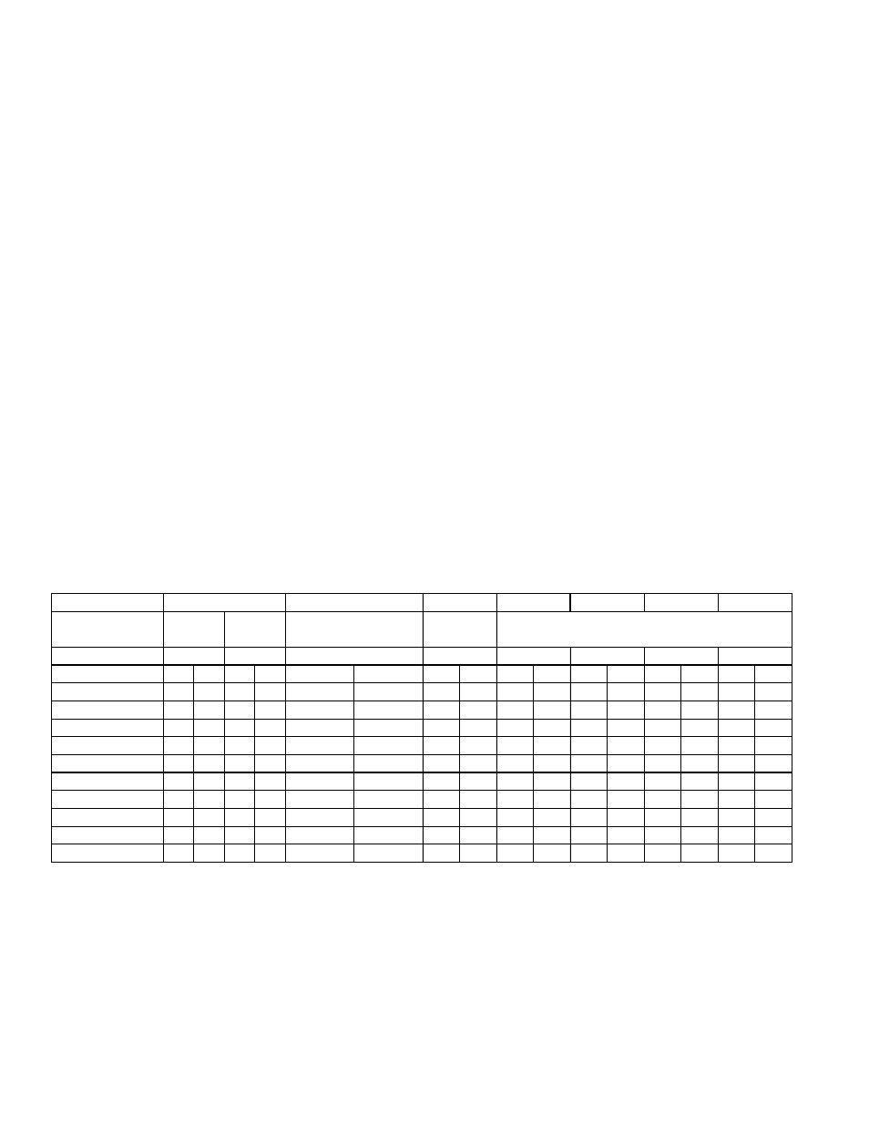
The table below lists the minimum supply pressure required for manifold and
gas control combinations. Refer to the wiring diagram to be sure which combi-
nation of options applies to the system being serviced. (NOTE: Not all options
are applicable on all models.)
OPERATION/SERVICE SECTION (cont'd)
Minimum Supply Gas Pressure ("w.c.) for Full Fire
Manifold Option
with Gas Control
Option
Manifold Size
MBH
Nat Pro Nat Pro
Nat
Pro
Nat
Pro
Nat
Pro
Nat
Pro
Nat
Pro
Nat
Pro
250
4.0
1.4
4.0 N/A
4.1
1.6
4.3
1.5
4.4
1.6
4.6
1.6
4.5
1.6
5.1
1.8
500
5.3
1.9
5.0 N/A
5.8
2.3
6.2
2.2
6.0
2.3
5.2
1.9
5.0
1.7
5.3
1.9
750
7.5
2.7
6.8 N/A
8.5
3.3
9.5
3.3
8.4
3.3
6.1
2.3
5.7
2.0
5.5
1.9
1000
12.4
4.7
11.7
4.6
7.4
2.8
6.7
2.4
5.8
2.1
1250
9.1
3.5
8.0
2.9
6.2
2.2
1500
11.2
4.3
9.6
3.5
6.6
2.4
1750
13.6
5.3
11.5
4.2
7.2
2.6
2000
16.5
6.3
13.7
5.0
7.8
2.8
2500
23.3
8.9
18.9
7.0
9.4
3.4
3000
11.3
4.1
AG1
BM75
1"
1-1/4"
AG3
AG 30, 31, 32, 33, 35,
36, 37, 47, 48, or 51
BM76
BM78
AG 49, 50
BM77
1-1/4"
2"
1"
1"
1"
1"
BM80
BM81
BM79
AG 30, 31, 32, 33, 35, 36, 37, 47, 48, or 51