Ignition system, Direct-fired burner – Reznor DV Operation Manual (for units built before August 2003) User Manual
Page 12
Form
O-DV/RDF/ADF, P/N 148385, Page 11
11. Ignition System
FIGURE 15 - Ignition
Control Module in the
Electrical Compartment,
P/N 157953
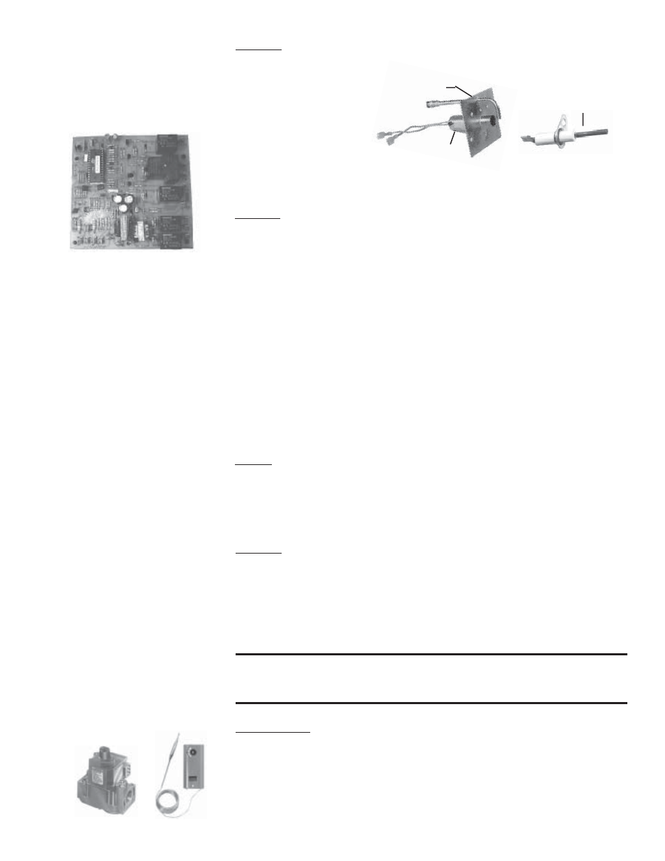
FIGURE 16 - Ignitor,
P/N 121865, and Flame
Sensor, P/N 134706, on
the Burner
Location: Ignition Controller Module in the Control Compartment Electrical
Box (See FIGURES 9 and 15.); Ignitor and Flame Sensor on the Burner (See
FIGURE 16.)
Hot Surface Ignition System with Prepurge Time Delay and
Flame Sensor with 100% Lockout
Function: The ignition system including the controller, the hot surface ignitor,
and the flame sensor function to ignite and prove the pilot flame. When there
is a call for heat, the modular ignition controller is energized. When the con-
troller reads 1.4 amps going to the hot surface ignitor, it opens the pilot valve
for a 15-second trial for ignition. After the pilot flame rod senses pilot flame,
the main gas valve is energized.
If the pilot flame rod does not sense a pilot flame, the controller shuts down the
pilot valve for a 10-second interpurge and then opens it again for a second
ignition trial. If pilot flame is not proven on the second trial, the ignition con-
troller locks out and must be manually reset by an interruption of the main
circuit (disconnect switch).
If the burner ordered is over three feet long (Model RDF with burner Option
BL7, BL8, BL9, BL10, BL11, or BL13), a second flame rod is located at the
end of the burner. After the main gas valve(s) is energized, a 15-second trial to
prove the second flame is initiated. Failure to recognize and prove flame travel
to the opposite end of the burner will result in a pre-purge and re-try for igni-
tion.
Service: The modular ignition controller does an internal self-check each time
that it is energized and will lockout if not found to be functioning properly. If
the ignition controller locks out and there is no other cause, the controller
module must be replaced.
12. Gas Train Includ-
ing Direct-Fired
Burner, Gas Con-
trol Systems,
Manifold
Arrangements, &
Gas Pressure
Switches
Direct-Fired Burner
Function: The design of the direct-fired burner and the controlled velocity of
air at the burner ensure complete combustion through the full range of burner
sizes and gas inputs as determined by the gas control system. The velocity of
air is controlled by the profile plates and monitored by a standard low and high
air pressure switch.
Service: Refer to Paragraph 6 in the Maintenance Section for instructions on
burner maintenance.
WARNING: Burner profile plates are factory set to match CFM
requirements. Do not adjust profile plates without contacting
your Sales Representative for technical assistance.
Makeup Air (100% Outside Air) Gas Control Systems
Single-Stage Gas Valve for Makeup Air (Option AG1)
(750MBH maximum)
The standard 24-volt, single state gas valve has an integral automatic electric
on-off valve, a pressure regulator, a safety pilot valve, and a manual shutoff.
The valve operates in response to a call for heat from a unit-mounted air con-
FIGURE 17 - Single-Stage
Gas Valve and Discharge
Air Controller in Makeup
Air Gas Control System,
Option AG1
Ignitor
○
○
○
Flame Sensor
Pilot Plate Assy
○
○
○
○
○
○
○
○
○
○○