Reznor DV Operation Manual (for units built before August 2003) User Manual
Page 18
Form
O-DV/RDF/ADF, P/N 148385, Page 17
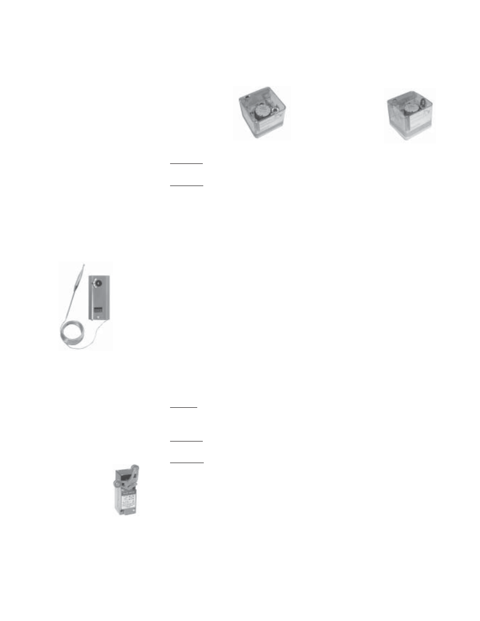
14. Door Switch
(Option BX1)
FIGURE 31 -
Door Switch,
P/N 124253
Location: The control is installed on an overhead door opening to control the
operation of the heater to coincide with the opening and closing of the door.
Function: The function of the switch is to energize and interlock the heating
unit when an outside overhead door reaches approximately 80% of full open
travel. The switch will de-energize the furnace when the overhead door closes
approximately 20%. The complete switch includes a limit switch electrically
wired to the heater and a roller yoke for mechanical activation by a field-
supplied trigger on the overhead door.
13. Outside Air
Cutoff Control
(Option BN2)
Location: The control is in the electrical box (See Figure 7.); the sensor is in
the air inlet.
Function: After sensing pilot flame, the burner ignites at its lowest input rate.
The "amount of heat" required to reach the desired discharge temperature also
depends on the temperature of the incoming outside air. The outside air con-
trol is factory set at 60°F (adjustable 25-250°F). The burner reacts differently
depending on the entering air temperature and the setting on the outside air
control. The burner --
• may not ignite (pilot valve will not open);
If the actual temperature of the outside air is above the setpoint on the
outside air control, the burner will not ignite.
• may modulate to satisfy discharge setting;
• would shutdown completely only on Option BN2 control, once burner has
been fired; or
Modulating operation will depend on the temperature rise between the
outside air and the discharge air setting.
• may remain on continuous low fire.
If the outside air control is set too high, the burner will continuously burn
on low fire as long as the control switch is set to "winter".
When the outside air control is set properly for the climate, the system blower
will continue to provide the required makeup air (ventilation) at the ambient
outdoor temperature (burner not operating) even when the control switch is
set to "winter".
Service: If the control does not function properly, replace it with an identical
switch.
FIGURE 30 - Outside Air
Cutoff Control, P/N 126170
FIGURE 29 - Gas
Pressure Switches
Low Gas
Pressure
Switch,
P/N 204375
(automatic)
High Gas
Pressure
Switch,
P/N 204297
(manual reset)
pressure switch will automatically reset when the gas pressure rises above the
setpoint.
(NOTE: Both high and low gas pressure switches incorporate a vent limiting
device and do not require venting to the outdoors when used in an application
indoor installation.)
Description: The system is equipped with one of the 11 types of inlet air
control arrangements listed below. All systems provide a constant flow of out-
side air across the burner at the required air volume (CFM). Refer to the wiring
diagrams in the main electrical box to determine which controls are on the
system being serviced.
15. Inlet Air Controls