Air pressure switches – Reznor DV Operation Manual (for units built before August 2003) User Manual
Page 11
Form
O-DV/RDF/ADF, P/N 148385, Page 10
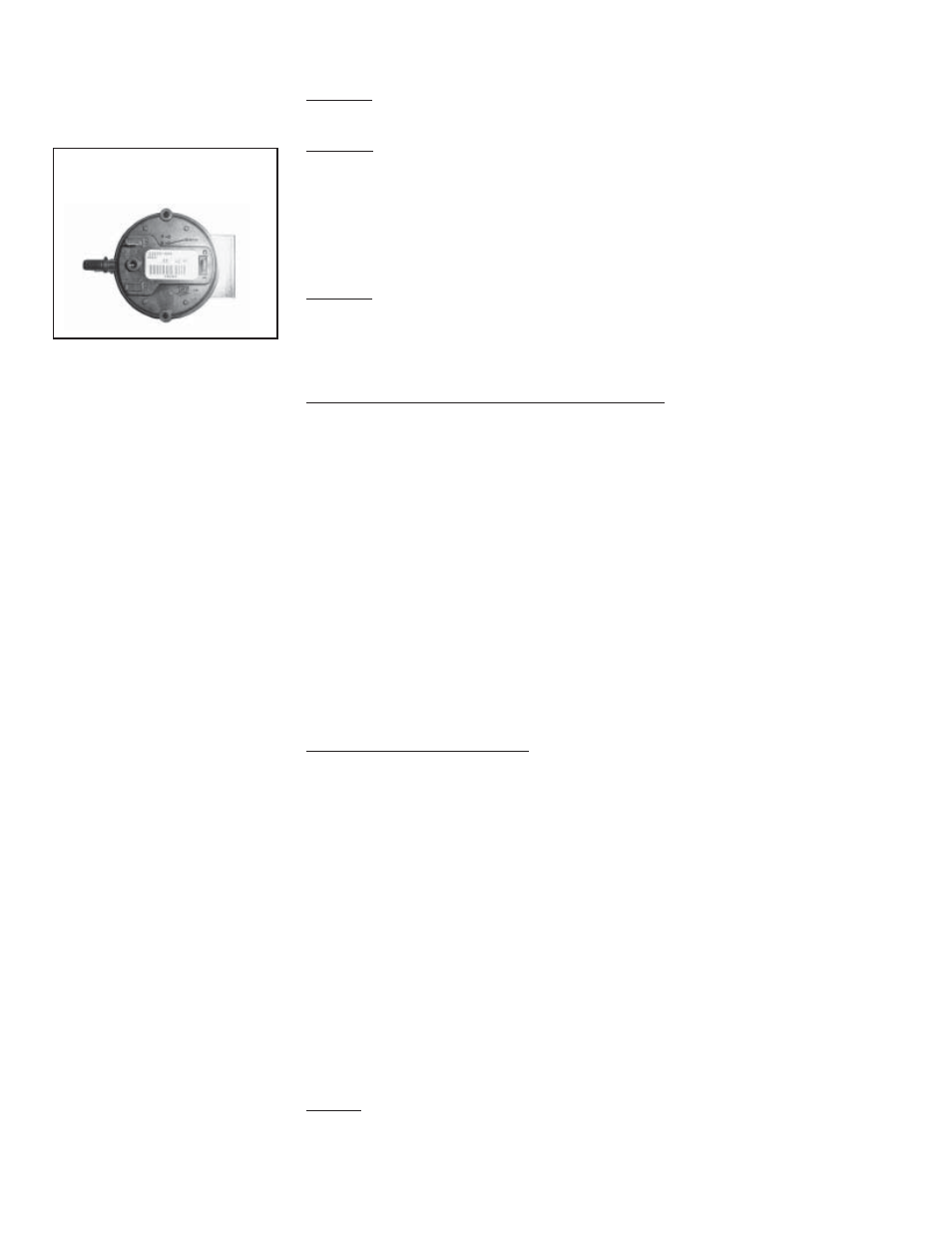
FIGURE 14 - Air
Pressure Switch
10. Air Pressure
Switches
Location: Control Compartment Electrical Box (See FIGURE 7.)
• Low Airflow Switch
Function: The low airflow switch is a velocity pressure switch that monitors
airflow across the burner. Until the airflow attains adequate volume for com-
bustion, the switch remains open. When the switch recognizes adequate air
volume, it closes, permitting both the pilot and burner to operate. Low pres-
sure switch is normally open; it closes on pressure rise at .25" w.c. Do not alter
or adjust setting.
• High Airflow Switch
Function: The high airflow switch is a velocity pressure switch that monitors
airflow across the burner. If the high airflow switch senses air velocity above
the prescribed limit, it will shutdown gas flow to the burner. High pressure
switch is normally closed; it opens when pressure rises above .75" w.c. Do not
alter or adjust setting.
Low and High Airflow Sensing Pressure Check: (requires slope gauge, sev-
eral feet of 1/4" OD tubing and two 1/4" OD barbed tees.)
Attach a slope gauge (0 to 1.0" scale) to the tubing connections in the control
compartment. The two connections are located below the electrical control
box. Remove the caps on the 1/8" NPT test connections and attach the slope
gauge. (The recommended method for attaching the slope gauge is to use field-
supplied 1/8" female NPT x 1/4" O.D. barbed hose connections.)
A) If the system includes an optional discharge damper, before measuring burner
differential air pressure, check to be sure that the damper is fully open.
B) With the blower operating, the pressure differential on the slope gauge should
read between -.25" and -.75" w.c. If the slope gauge reading is within those
limits, no adjustments are necessary.
C) When air pressure is within the proper range, turn the disconnect switch OFF.
Disconnect the manometer and the slope gauge. Replace the caps removed to
connect the slope gauge.
Pressure Switches and Bypass Damper Airflow (Applies to
Model DV or Model RDF systems with Air Control Options
AR19, AR20, AR22, AR23, AR32, AR33, AR34, AR36, or AR37)
Adjustment of the bypass damper is controlled by the same low and high pres-
sure switches described above. With a bypass damper, the volume of outside
air supplied to the building is controlled by a manually set potentiometer (Op-
tion AR19 and AR22) or automatically by a pressure null switch (Option AR20
or AR23), a photohelic pressure switch (Option AR36 or AR37), or a field-
supplied computer signal (Option AR33 or AR34). With Options AR19, AR20,
AR33, and AR36 the supply air is varied by adjusting the position of a damper
at the blower discharge. With Options AR22, AR23, AR34, and AR37, a return
air damper is adjusted to vary the volume of return air. The unit is arranged so
that a fixed amount (20%) of the rated volume flows over the burner at a con-
stant velocity. The remainder (80%) of the rated air volume flows either through
a balancing bypass damper or a combination of bypass and return air dampers.
As the supply air volume is varied by the return air or discharge damper, the
balancing damper is adjusted to maintain the required air velocity over the
burner. See Paragraph 14 for inlet air control options.
Service: If the pressure check determines that an airflow switch is not func-
tioning properly, the switch cannot be serviced and must be replaced with an
identical replacement. Low air pressure switch is P/N 203932; high air pres-
sure switch is P/N 203933.
OPERATION/SERVICE SECTION (cont'd)