3 limit safety controls, 4 air pressure switches – Reznor ADFH Operation Manual User Manual
Page 9
Form O-ADF/RDF, P/N 148385R2, Page 9
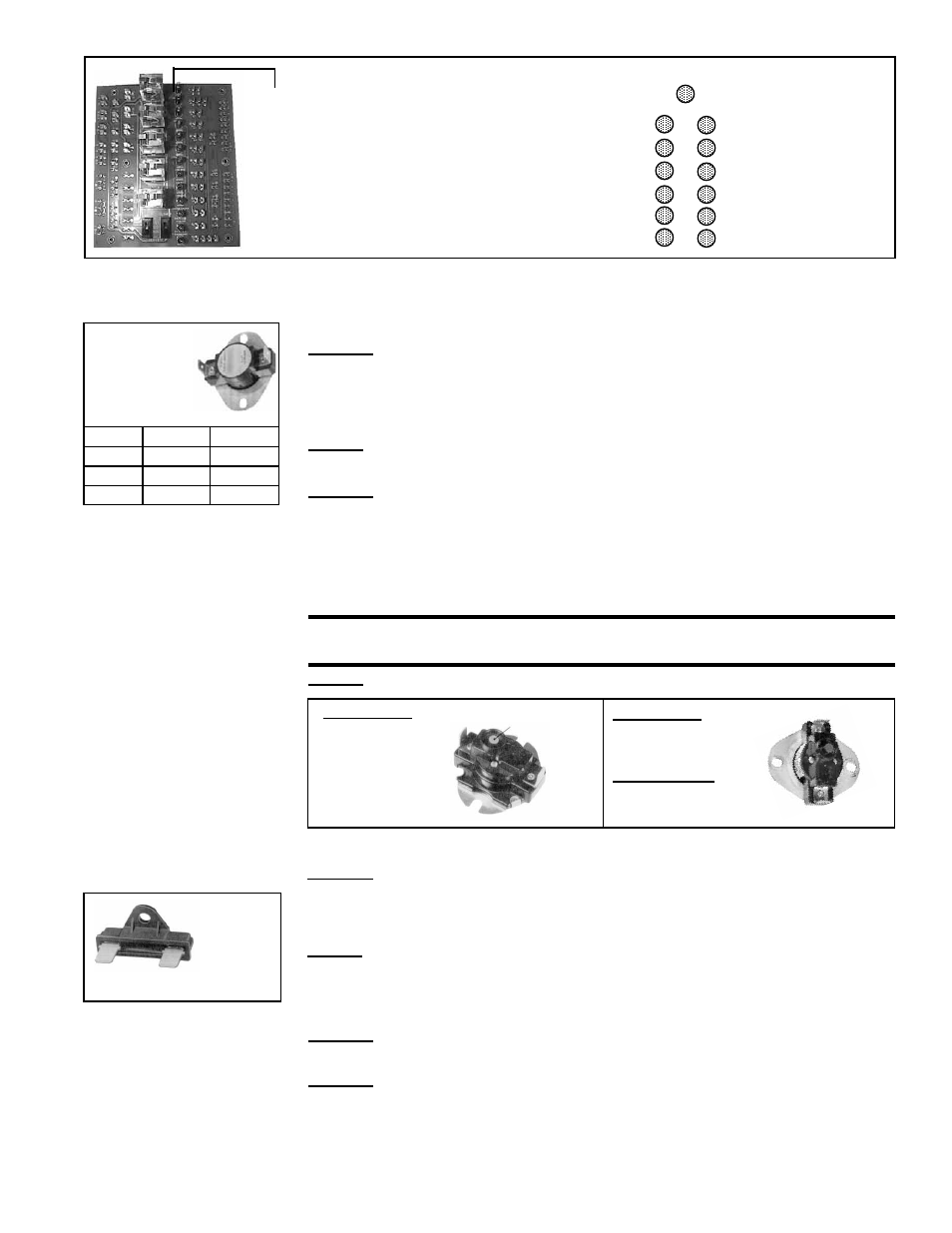
Column of 13
indicator bulbs;
always replace
burned out bulbs,
P/N 125189.
Control Circuit Power
Control Switch Energized
Firestat Normal
Freezestat Normal
Starter Energized
Blower ON - Low Air Pressure Normal
Blower ON - High Air Pressure Normal
Manual and Auto Limits
Normal
Outside Air Cutoff Normal
Low Gas Pressure Normal
High Gas Pressure Normal
Pilot Valve Energized
Gas Safety Valve Energized
FIGURE 10 - Diagnostic Circuit Board, P/N 151263
3.3 Limit Safety
Controls
Each unit has an automatic temperature activated limit control, a manual reset tem-
perature activated limit control, and an electrical activated energy cutoff device.
• Automatic Reset Limit Control
Function: If the temperature of the discharge air reaches the setpoint, the limit will
open the circuit to the burner system and close all burner and pilot valves. The limit
control will be activated if total airflow is reduced or if gas pressure surges at the burner
causing excessive discharge air temperature. The system will restart when the dis-
charge air temperature decreases below the setpoint.
Service: Failure of this limit requires replacement of the control.
FIGURE 11 -
Automatic
Reset Limit
Controls
Model
P/N
Setting
RDF
86979
135°F
ADF
122856 130°F
ADFH
57953
170°F
• Manual Reset Limit Control
Function: The manual reset limit has a higher setting than the automatic limit and
requires manual resetting to restart the system. If for any reason the automatic limit
should fail to protect against overheating, the manual limit will shutdown the system.
Should the manual reset limit activate, check the entire system to determine the cause.
Make any necessary changes or adjustments before restarting the burner system.
Restart of the unit can be done only after the limit has been cooled and the reset but-
ton depressed.
CAUTION: If the manual reset limit activates, find and correct the
cause before restarting the system.
Service: Failure of this limit requires replacement of the control.
FIGURE 13 - ECO Limit
Control
Setting
305°F
FIGURE 12 - Manual
Reset Limit Controls
Model RDF -
Setting 150°F,
P/N 82610
Model ADF -
Setting 135°F,
P/N 122858;
Model ADFH -
Setting 175°F,
P/N 122990
• Emergency Cut Off Limit Control
Function: The emergency cut off is a fusible link high temperature limit which pro-
vides onetime redundant protection against overheating. If the temperature sensitive
limit controls malfunction, the electrically activated emergency cutoff will shutdown the
system.
Service: If this limit activates, the manual limit control has failed and must be replaced.
The cause for activating the emergency cut off limit control must be found and cor-
rected before re-starting the system.
P/N 82414
3.4 Air Pressure
Switches
Location: Control Compartment Electrical Box (See FIGURE 9.)
• Low Airflow Switch
Function: The low airflow switch is a velocity pressure switch that monitors airflow
across the burner. Until the airflow attains adequate volume for combustion, the switch
remains open. When the switch recognizes adequate air volume, it closes, permitting
both the pilot and burner to operate. Low pressure switch is normally open; it closes on
pressure rise at .25" w.c. Do not alter or adjust setting.
Reset Button