0 maintenance (cont'd), 0 operation and service, 3 maintenance procedures (cont'd) – Reznor ADFH Operation Manual User Manual
Page 8: 1 control locations, 2 electronic circuit board with lights
Form O-ADF/RDF, P/N 148385R2, Page 8
2.0 Maintenance
(cont'd)
2.3 Maintenance
Procedures
(cont'd)
2.3.7 Optional Evaporative Cooling Module (cont'd)
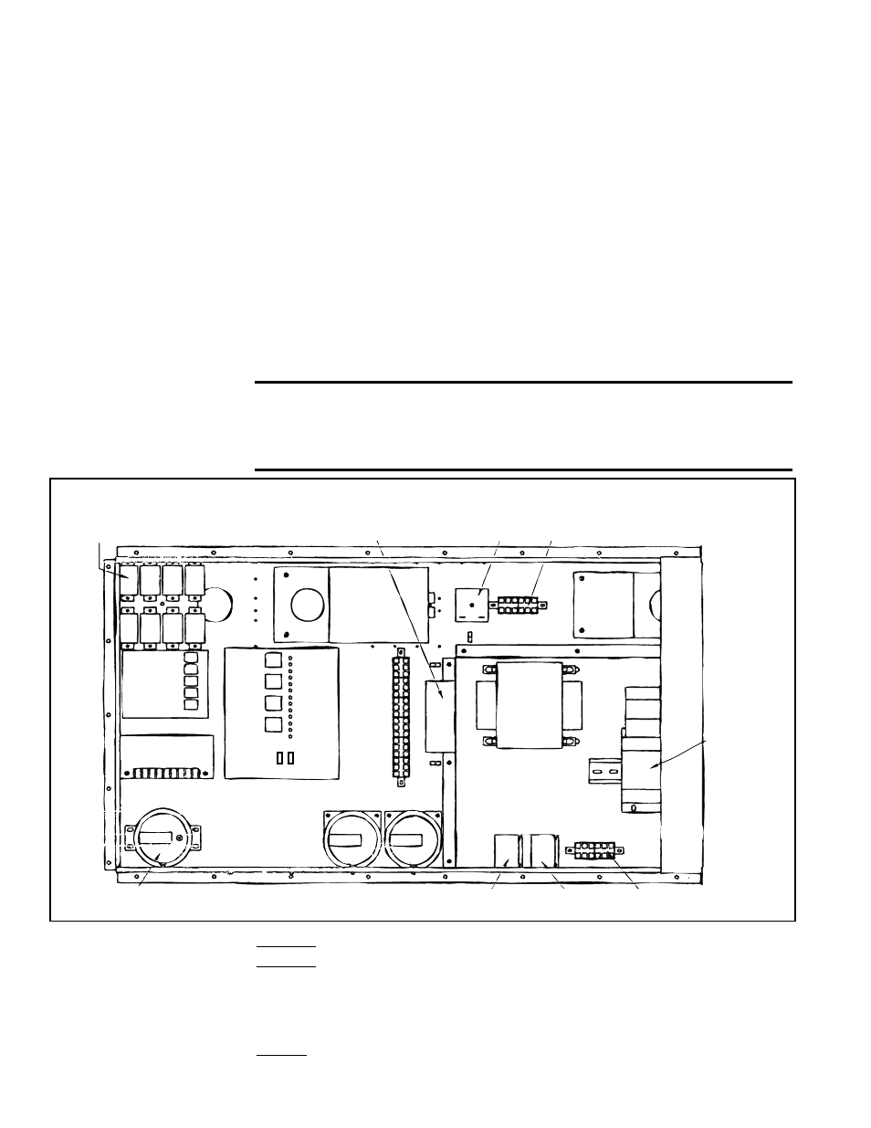
FIGURE 9 - Control Identification and Typical Locations
Control
Relays
Outside Air Cutoff
(high ambient limit control)
Time Delay
Relay
24-volt Terminals
Ignition
Module
Maxitrol Amplifier
or Signal
Conditioner
Service
Switches
St
atus Light
s
Circuit
Board
24-V
olt T
erminals
Bypass
Damper
Motor
Return
Air
Damper
Motor
Motor
Starter
Transformer
Line Voltage
Terminals
Starter
Relay
Relay for
Optional 2-Speed
High
Low
Standard
Pressure
Switches
Optional Dirty Filter
Pressure Switch
3.0 Operation and
Service
3.1 Control Locations
To service this system, it is necessary to understand the normal operation of the con-
trols and the function of the diagnostic circuit board. Refer to the electrical box drawing
in
FIGURE 9 and to the individual illustrations to identify and locate each of the con-
trols. The wiring diagrams for this unit are located in the main electrical box.
WARNING: Service work on this system should only be done
by a qualified gas service person. The service information and
the troubleshooting guides are intended as an aid to a qualified
service person.
3.2 Electronic
Circuit Board
with Lights
Location: Control Compartment Electrical Box (See FIGURE 9)
Function: The diagnostic lights on the circuit board are designed to assist in trouble-
shooting. When the system is operating properly, the lights on the circuit board are lit.
If the system fails to operate properly, all lights on the circuit board up to the one that
represents the component or system that has failed will be lit. For more detailed infor-
mation, refer to the Troubleshooting Guide in Paragraph 3.9..
Service: Replacing burned out bulbs is the only service required. If a bulb is not lit,
check the bulb by switching it with a bulb that is lit.
2. Remove the service panel and the junction box door. Disconnect the two-line
voltage power supply wires from the terminal block inside the junction box.
3. Disconnect the water feed line hose from the upstream side of the ball valve.
4. Unscrew the four sheetmetal screws holding the junction box to the cooling
module. Remove the junction box-pump-float switch assembly (See
FIGURE 8).
5. Dislodge the inlet basket screen from the pump and clean any buildup of debris
and dirt. Carefully remove the base cover plate from the bottom of the pump. Using
a mild soap solution, wash all deposits from the inside of the pump and remove all
debris from the impeller.
6. Reassemble the pump. Replace the parts in exact reverse order, being careful that
everything is returned to its proper position.