Reznor ADFH Operation Manual User Manual
Page 11
Form O-ADF/RDF, P/N 148385R2, Page 11
If the pilot flame rod does not sense a pilot flame, the controller shuts down the pilot
valve for a 10-second interpurge and then opens it again for a second ignition trial. If
pilot flame is not proven on the second trial, the ignition controller locks out and must
be manually reset by an interruption of the main circuit (disconnect switch).
If the burner ordered is over three feet long (Model RDF with burner Option BL7, BL8,
BL9, BL10, BL11, or BL13), a second flame rod is located at the end of the burner.
After the main gas valve(s) is energized, a 15-second trial to prove the second flame is
initiated. Failure to recognize and prove flame travel to the opposite end of the burner
will result in a pre-purge and re-try for ignition.
Service: The modular ignition controller does an internal self-check each time that it is
energized and will lockout if not found to be functioning properly. If the ignition control-
ler locks out and there is no other cause, the controller module must be replaced.
3.6 Gas Train
Including
Burner, Gas
Controls,
Manifold
Arrangements,
and Gas
Pressure
Switches
Direct-Fired Burner
Function: The design of the direct-fired burner and the controlled velocity of air at the
burner ensure complete combustion through the full range of burner sizes and gas
inputs as determined by the gas control system. The velocity of air is controlled by the
profile plates and monitored by a standard low and high air pressure switch.
Service: Refer to Paragraph 2.3.6 for instructions on burner maintenance.
WARNING: Burner profile plates are factory set to match CFM
requirements. Do not adjust profile plates without contacting your
Sales Representative for technical assistance.
Makeup Air (100% Outside Air) Gas Control Systems
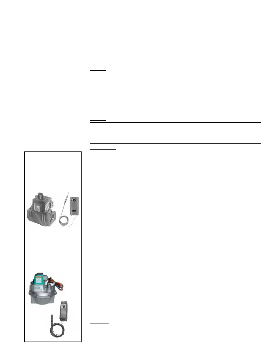
• Single-Stage Gas Valve for Makeup Air (Option AG1) (750MBH
maximum)
The standard 24-volt, single state gas valve has an integral automatic electric on-off
valve, a pressure regulator, a safety pilot valve, and a manual shutoff. The valve oper-
ates in response to a call for heat from a unit-mounted air controller that monitors dis-
charge air temperature. The controller has a built-in setpoint selector from 0° - 100°F.
Due to different CFM settings and outside temperatures, the average downstream
outlet temperature may not match the control setting exactly. After the installation is
complete, adjust the setpoint to achieve the desired average outlet air temperature.
See the valve manufacturer's literature provided in the owner's envelope for specifica-
tions, wiring, and operating information.
• Two-Stage Gas Valve for Makeup Air (Option AG3) (750 MBH
maximum)
The single-stage valve is replaced by a two-stage valve having low fire and high fire
operation. The two-stage valve is controlled by a unit-mounted ductstat that monitors
discharge air temperature. The ductstat has a built-in setpoint selector from 60°-110°F.
Available for use with natural gas only.
Due to different CFM settings and outside air temperatures, the average downstream
outlet temperature may not match the ductstat setting exactly. After the installation is
complete, adjust the setpoint of the ductstat to achieve the desired average outlet air
temperature. See the valve manufacturer's literature provided in the owner's envelope
for specifications, wiring, and operating information.
• Electronic Modulation Gas Control for Makeup Air (100% Outside Air),
Options AG30, AG31, AG32, AG33, AG35, AG36
Refer to the wiring diagrams in the main electrical box to determine which controls
are on the system being serviced.
NOTE: All field-supplied control wiring for Maxitrol
controls must
not be run inside conduit with line voltage wiring. To avoid any potential
electrical interference, all field-supplied wiring for Maxitrol controls should be shielded
wiring and must be grounded at the unit only.
Function: These gas control systems provide heated makeup air at a temperature
controlled by a discharge air sensor. Makeup air gas controls apply only to systems
with 100% outside air. Each system is equipped with electronic modulation controls
that modulate burner flame from 1/25th of full fire input to full fire.
FIGURE 17 - Single-
Stage Gas Valve and
Discharge Air
Controller in Makeup
Air Gas Control
System, Option AG1
FIGURE 18 - Two-
Stage Gas Valve and
Discharge Ductstat
in Makeup Air Gas
Control System,
Option AG3