0 operation and service (cont'd), Maximum supply pressure by manifold – Reznor ADFH Operation Manual User Manual
Page 14
Form O-ADF/RDF, P/N 148385R2, Page 14
3.0 Operation and Service (cont'd)
3.6 Gas Train Including Burner, Gas Controls, Manifold Arrangements, and Gas
Pressure Switches (cont'd)
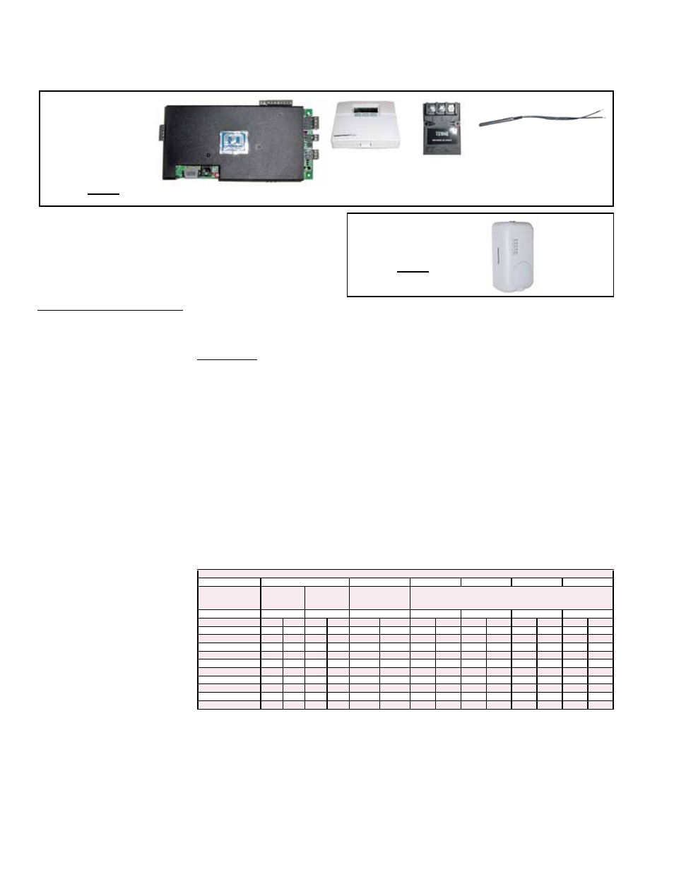
FIGURE 27 -
Maxitrol Series
44 Components
used in
Recirculation
Air Gas Control
Option AG48
Amplifier, P/N 204450
Selector,
P/N 204451
Return Air Sensor,
P/N 204452
Outside Air Sensor,
P/N 204452
Discharge
Air Sensor,
P/N 204453
Service - ALL Gas Controls: Check all electrical connections. A qualified service person should refer to the control
manufacturer's literature for assistance in identifying problems and determining the correct solution. None of the controls
have field replaceable parts. All components must be replaced with identical replacement parts.
Option AG51 electronic
modulation system is
comprised of the same
Maxitrol Series 44 controls
as Option AG48 plus a
remote sensor/selector.
FIGURE 28 - Option
AG51 includes Maxitrol
Series 44 Components
used in AG48 plus a
Remote Sensor
Remote
Sensor/
Selector,
P/N 204456
Manifold Arrangements
Description: The manifold is the gas train from the gas supply connection to the
burner. The manifold selection ordered determines the manifold arrangement including
all of the gas train components except the main control valve. Manifold arrangements
are available for varying BTUH ranges and gas controls and meet ANSI, CSA, FM or
GAP (former IRI) requirements.
All manifold arrangements include two 5psi rated manual shutoffs.
These systems are designed to operate on a natural gas supply differential pressure
range of a minimum of 4.3-5.0" w.c. plus the manifold pressure drop. Maximum sup-
ply pressure depends on manifold selection; see below. If the gas supply pressure is
above the maximum allowed, it is necessary to install a field-supplied step-down gas
regulator in the supply line. Order and install the appropriate Gas Regulator Kit, Option
CZ1 (1") or CZ2 (1-1/2"). Follow the instructions provided with the kit. Measure the gas
pressure between the step-down regulator and the unit.
The table right lists the
minimum supply pressure
required for manifold and
gas control combinations.
Refer to the wiring diagram
to be sure which combina-
tion of options applies to the
system being serviced.
Minimum Supply Gas Pressure ("w.c.) for Full Fire
Manifold Option
BM75
BM76
BM78
BM79
BM80
BM81
with Gas Control
Option
AG1
AG3
AG 30, 31, 32, 33,
35, 36, 37, 47, 48,
or 51
AG 30, 31, 32, 33, 35, 36, 37, 47, 48, or 51
Manifold Size
1"
1"
1"
1"
1-1/4"
1-1/4"
2"
MBH
Nat
Pro
Nat
Pro
Nat
Pro
Nat
Pro
Nat
Pro
Nat
Pro
Nat
Pro
250
4.0
1.4
4.0
N/A
4.1
1.6
4.4
1.6
4.6
1.6
4.5
1.6
5.1
1.8
500
5.3
1.9
5.0
N/A
5.8
2.3
6.0
2.3
5.2
1.9
5.0
1.7
5.3
1.9
750
7.5
2.7
6.8
N/A
8.5
3.3
8.4
3.3
6.1
2.3
5.7
2.0
5.5
1.9
1000
12.4
4.7
11.7
4.6
7.4
2.8
6.7
2.4
5.8
2.1
1250
9.1
3.5
8.0
2.9
6.2
2.2
1500
11.2
4.3
9.6
3.5
6.6
2.4
1750
13.6
5.3
11.5
4.2
7.2
2.6
2000
16.5
6.3
13.7
5.0
7.8
2.8
2500
23.3
8.9
18.9
7.0
9.4
3.4
3000
11.3
4.1
Maximum Supply
Pressure by Manifold
If the gas train includes either or both high and low gas pressure switches, the switches
monitor gas pressure downstream from the safety valves.
If the gas pressure in a system equipped with a high gas pressure switch (standard
with manifold Options BM 78, 79, 80 and 81; Option BP2 with other manifolds) exceeds
the setpoint, the switch will open the electrical circuit to the burner, stopping all gas
flow. The high gas pressure switch is a manually reset device.
A low gas pressure switch (Option BP3) will shutoff the gas flow if the gas pressure
drops below the setpoint of the low pressure switch. The low gas pressure switch will
automatically reset when the gas pressure rises above the setpoint.
(Refer to the wiring diagram or rating
plate to identify the manifold on the
system being serviced.)
Manifold Option BM75, BM76 - 1/2 psi
Manifold Option BM78, BM79 - 2 psi
Manifold Option BM80, BM81 - 5 psi