References – Reznor ADFH Operation Manual User Manual
Page 19
Form O-ADF/RDF, P/N 148385R2, Page 19
15. Disconnect closed; blower and burner switches in run
position; control switch is in "winter" position; all status lights
are lit except "main valve normal" light. The pilot flame is
present and stable, but the (low stage portion or) main gas
valve will not open, or rapid cycling of the main valve is
occurring.
1. Microamp signal on flame rod is inadequate - check position and condition of flame
rod and signal (minimum 0.5 microamps required.)
2. Grounding for unit or flame rod inadequate - check ground path.
3. Faulty main gas valve - replace main gas valve.
4. Faulty ignition module - replace ignition module.
5. Inadequate main gas pressure - verify main burner pressure.
16. Disconnect closed; blower and burner switches in run
position; control switch is in "winter" position; all status lights
are lit; the pilot flame and low fire on the main burner are
present and stable, but the unit will not progress to a high
fire condition.
1. Faulty main gas valve - replace main gas valve.
2. Inadequate timing on high fire time delay relay - adjust setting.
3. Faulty high fire time delay relay - replace time delay relay.
4. High stage relay contacts are not closed - check control setting.
5. Inadequate main gas pressure - verify main burner gas pressure.
6. Faulty high stage relay - replace relay.
7. Faulty ignition module - replace entire module.
REFERENCE: For service and troubleshooting information on the electrical controls, refer
to the manufacturer's literature covering that component. Component literature is included
in the literature envelope.
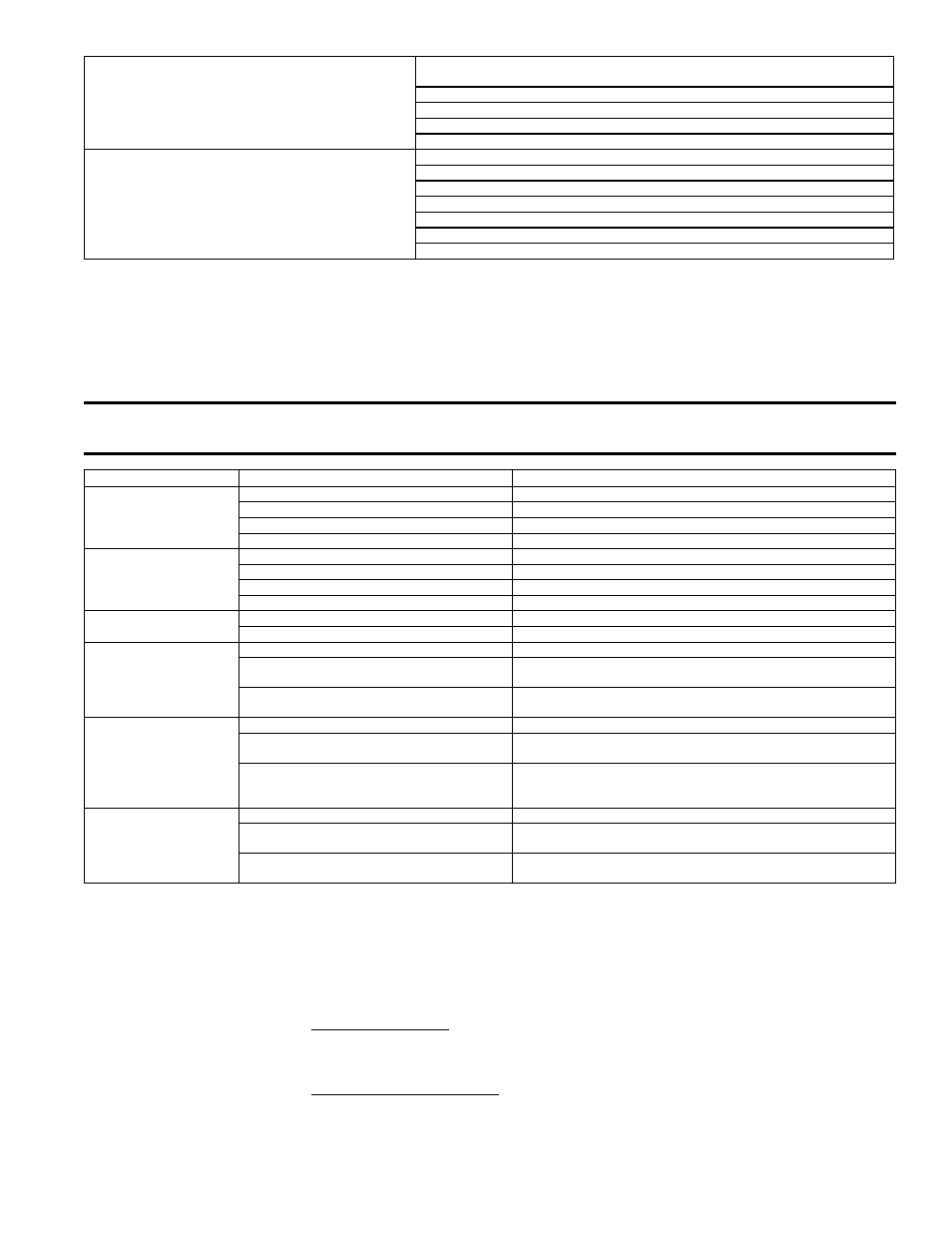
Chart 2 - Troubleshooting Optional Evaporative Cooling Module
WARNING: Disconnect the power before servicing the cooling module. Failure to do so can
cause electrical shock, personal injury or death.
Problem
Probable Cause
Remedy
Float & Pump Control Sys-
tem - Pump does not run.
Control is calling for cooling
and reservoir is full.
1. Electrical connections
1. Verify all electrical connections. See Wiring Diagram.
2. Electric float switch on pump
2. Check position of the actuators on the electric float switch.
3. Dirty pump
3. Clean pump. See Paragraph 2.3.7.
4. Defective pump
4. Replace pump.
Float & Pump Control Sys-
tem - Required water level
(3") not maintained
1. Float valve
1. Adjust float valve. Refer to the installation manual.
2. Optional drain and fill valves
2. Check valve for proper operation.
3. Incorrect overflow pipe nipple - should be 3-1/2" 3. Replace pipe nipple.
4. Drain leaking
4. Tighten drain plug.
Water running off of media
pads
1. Excessive water flow
1. Adjust ball valve in distribution line. Refer to installation manual.
2. Media pads need cleaned or replaced.
2. Clean or replace media pads. See Paragraph 2.3.7.
Water not distributing
evenly
1. Distribution line clogged
1. Flush distribution line. See Paragraph 2.3.7.
2. Holes in distribution line turned
2. Check position of distribution line. Holes should be spraying upward.
If not positioned with holes toward top, adjust position of PVC line.
3. Incorrect voltage to pump (float and pump
control system)
3. Check voltage at pump terminal in cooling module junction box.
Media pads becoming
clogged and discolored
quickly (scale/salt deposits)
and/or rapid deterioration of
the float switch (Float and
Pump Control System)
1. Bleed off line clogged
1. Clean bleed line.
2. Excessive water flow
2. Reduce flow by adjusting ball valve in distribution line. Refer to
installation manual.
3. Inadequate bleed off
3. A uniform build-up of minerals on the entering air face of the media
indicates insufficient bleed off. Increase the rate until the mineral
deposits dissipate.
Water blowoff from media
pads or water being pulled
from reservoir
1. Media pads installed incorrectly
1. Install media pads correctly. See Paragraph 2.3.7.
2. Requires moisture elimination pad (over 600
FPM)
2. Install moisture elimination pad. Consult factory.
3. Water level not 3 inches (float and pump control
system)
3. See second problem listed above (Required water level not being
maintained.)
The following forms are available at www.RezSpec.com:
Installation Manuals:
Model RDF,
Form I-RDF
Models ADF/ADFH,
Form I-ADF
Replacement Parts Manual:
Form P-ADF/DV/RDF
References