Reznor ADFH Operation Manual User Manual
Page 5
Form O-ADF/RDF, P/N 148385R2, Page 5
S
2.3.4 Air
Pressure
Profile plate sensing tubes should be checked quarterly and cleaned no less than
semi-annually. If the sensing tubes become even partially blocked, false pressure
readings may be relayed.
To clean, remove the screened end caps and clean the screens and the tubes. Replace
the clean end caps. Check the pressure differential across the profile plate using a
slope gauge. To attach the slope gauge, open the control compartment door panel.
Just below the junction box, locate the tubing connections. Remove the cap at each
connection and attach the slope gauge using two field-supplied 1/4" x 1/8" female NPT
barbed tubing connections. For instructions on measuring air pressure, see Paragraph
3.4. Air pressure differential should be between -.25" and -.75" w.c.
FIGURE 3 - Circuit Indicator
Board, P/N 151263
Check bulbs
not lit with other
bulbs; replace
any burned out
bulbs.
Row of Bulbs
R
2.3.5 Circuit
Indicator Board
(check lights)
The circuit indicator board is
located in the control compart-
ment electrical box (See
FIGURE
9, page 8). Check operation of all
indicator lights by switching lights
that are not lit with one that is cur-
rently lit. Replace any burned out
indicator bulbs (
P/N 125189).
2.3.6 Main
Burner and Pilot
Assembly
For the most part, the burner and pilot are self cleaning. However, if the application is
extremely dirty or dusty, cleaning of the burner and pilot may be necessary. Inspect the
burner annually. Follow these instructions. If it is necessary to replace any parts, use
only factory-authorized replacements.
1) Turn off the gas and power supply to the system.
2) Remove the door panels in the burner/control cabinet. Locate the pilot.
CAUTION: Wear eye
protection while
pressure cleaning
and drilling.
S
WARNING: Do not
enlarge burner ports
or performance
may be drastically
affected.
FIGURE 4 - Burner
End Plate showing Hot
Surface Ignitor
Flame Sensor (not
shown) Location
Burner
End Plate
NOTE: Model RDF units
manufactured prior to
3/96 have a spark ignition
system. Clean ultraviolet
sensor and spark plug.
Replace as needed.
WARNING: Burner
profile plates are
factory set to match
CFM requirements.
Do not adjust
profile plates
without contacting
your Sales
Representative for
technical assistance.
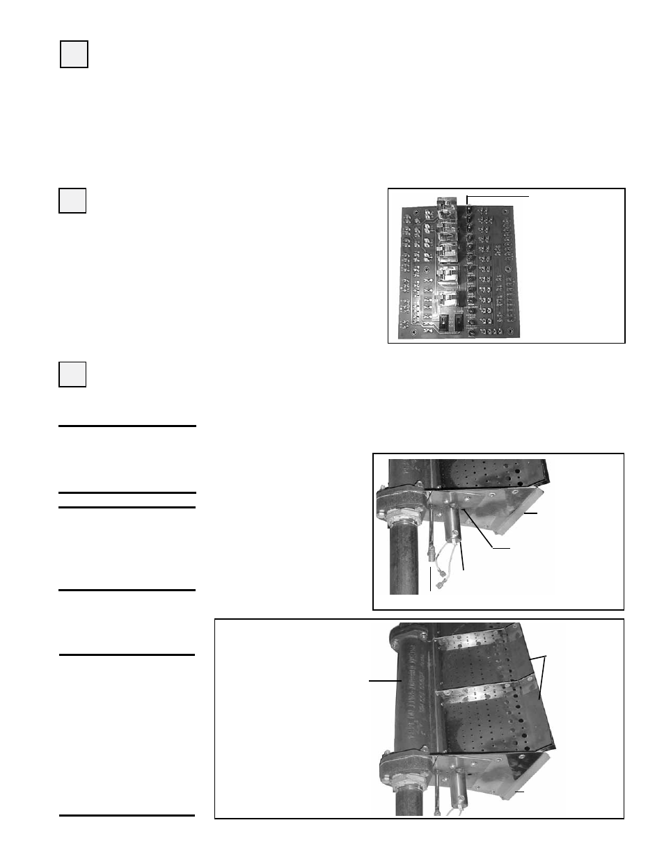
FIGURE 5 - Direct Fired
Burner
Ignitor
Mixing
Plates
Burner - Full length of
the burner is made up
of a series of 6" or 12"
burner sections.
Burner
End Plate
Pilot Tubing