0 maintenance (cont'd), 3 maintenance procedures (cont'd), 7 optional evaporative cooling module – Reznor ADFH Operation Manual User Manual
Page 6: 6 main burner and pilot assembly (cont'd)
Form O-ADF/RDF, P/N 148385R2, Page 6
2.3.7 Optional
Evaporative Cooling
Module
Media - Over time, excessive amounts of mineral deposits will begin to buildup on the
media. Annually, scale and dirt should be washed off the entering surface of the media.
Remove the pad retainers and screen. (See Steps 1-3 and 6-8 of Media Replacement
Instructions.) Clean the media using a garden hose, mild soap, and a soft bristled
brush. When the media becomes too clogged with mineral deposits and dirt that it can-
not be cleaned, the pads should be replaced. The average pad life is approximately
three cooling seasons.
See charts and
NOTE below for replacement media information. Follow the instruc-
tions and remove and replace pads as shown in
FIGURE 6.
R
E
Instructions
for Replacing
Evaporative Cooling
Media
1. Remove the three sheetmetal screws that hold the top pad retainer in place.
Release the top pad retainer from the cooling module.
2. Remove the three sheetmetal screws that hold the bottom pad retainer in place.
Release bottom pad retainer from the cooling module.
3. Disengage the screen retainers from the sides of the media.
4. Disengage inlet screen from media pads and remove.
5. Slide all media pads horizontally away from the cooling module until clear of
bottom reservoir pan. Dispose of properly.
2.0 Maintenance
(cont'd)
2.3 Maintenance
Procedures
(cont'd)
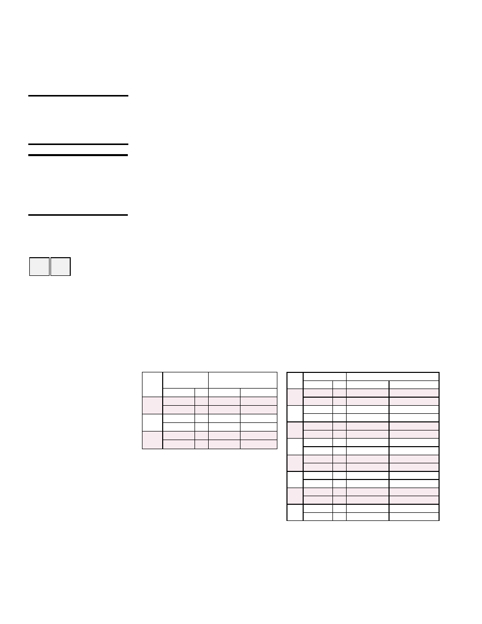
ADF /
ADFH
Media Pad
Size & Qty
Replacement P/N's
(each) - 12" media *
(inches) Qty Cellulose Glass Fiber
300
24 x 12
2
106021
106029
24 x 7-7/8 1
106022
106030
500
24 x 12
3
106021
106029
24 x 9-5/8 1
106025
106033
700/
1200
48 x 12
4
107194
107201
48 x 8-5/8 1
107195
107202
REC Media Pad
Replacement P/N's (each) *
Size
Qty 12” Cellulose 12” Glass Fiber
40
24x12
2
106021
106029
24x2-3/8 1
106022
106030
50
24x12
2
106021
106029
24x7-7/8 1
106023
106031
60
24x12
3
106021
106029
24x1-3/8 1
106024
106032
70
24x12
3
106021
106029
24x9-5/8 1
106025
106033
80
24x12
4
106021
106029
24x2-7/8 1
106026
106034
90
24x12
4
106021
106029
24x8-5/8 1
106027
106035
180
48x12
4
107194
107201
48x8-5/8 1
107195
107202
360
48x12
8
107194
107201
48x8-5/8 2
107195
107202
Evaporative Cooling Media -
Model ADF or ADFH with Option
AS3, AS4, AS5, or AS8
Evaporative Cooling Media - Model
RDF with attached Model REC
Evaporative Cooling Module
* NOTE: 6" media is no longer
available as a replacement part. Use
size to obtain media from a local
supplier.
2.3.6 Main Burner and Pilot Assembly (cont'd)
3) Disconnect the two ignition wires (male and female quick connections) and dis-
connect the flame sensor lead at the burner. Remove the setscrew located in the
ignitor tube (setscrew holds the brass bushing in place). Carefully remove the
brass bushing and the ignitor.
Check the hot surface ignitor for cracks or unusual deterioration. Check the flame
rod for integrity. Replace the flame rod (
P/N 134706) and/or the hot surface ignitor
(
P/N 121865) if not in good condition.
4) Clean the burner and pilot by back-flushing, using high pressure air (40-80 lbs).
Continue until dust particles are completely expelled from both the upstream and
downstream sides of the burner.
If air pressure does not unplug burner orifices or pilot tube, drill burner orifices with
a Size #50 drill and/or pilot tube with a Size #55 drill.
Inspect the upstream and downstream sides of the mixing plates. Remove any
accumulation of scale or foreign material with a wire brush. If any mixing plate fas-
teners are loose or missing, tighten or replace. Always use zinc plated or stainless
fasteners.
If any cracks are present, replace that mixing plate. Because of the effect of flame
temperature on the metal, fasteners may be difficult to remove. Be careful not to
damage the gaskets that go between the mixing plates and the burner body. The
gaskets are designed to overlap approximately 1/16" for airtight seal.
5) Follow Steps in reverse order to re-install the pilot assembly. Close all panels and
check for proper operation.
CAUTION: Wear eye
protection while
pressure cleaning
and drilling.
WARNING: Do not
enlarge burner ports
or performance
may be drastically
affected.