Warning – Reznor R6GF Unit Installation Manual User Manual
Page 8
8
CIRCULATING AIR SUPPLY
WARNING:
Do not allow combustion products to enter the
return air ductwork or the circulating air supply.
Failure to prevent the circulation of combustion
products into the living space can create
potentially hazardous conditions including
carbon monoxide poisoning that could result
in personal injury or death.
All return ductwork must be secured to the unit
with sheet metal screws. All return ductwork
must be adequately sealed and all joints must
be taped. When return air is provided through
the bottom of the unit, the joint between the
unit and the return air plenum must be air tight.
The roof curb or cement pad on which the unit is
mounted must provide sound physical support
of the unit with no gaps, cracks, or sagging
between the unit and the curb or pad.
Return air and circulating air ductwork must not
be connected to any other heat producing device
such as a fireplace insert, stove, etc. Doing so
may result in fire, explosion, carbon monoxide
poisoning, personal injury, or property damage.
Air Ducts
This unit is designed only for use with a supply and return
duct. Air ducts should be installed in accordance with the
standards of the National Fire Protection Association
“Standard for Installation of Air Conditioning Systems”
(NFPA 90A), “Standard for Installation of Residence Type
Warm Air Heating and Air Conditioning Systems” (NFPA
90B), and all applicable local codes. NFPA publications are
available by writing to: National Fire Protection Association,
Batterymarch Park, Quincy, ME 02269 or visit www.NFPA.
org on the web.
•
Design the duct work according to Manual D by the Air
Conditioning Contractors of America (ACCA).
•
The ducts must be properly sized not to exceed the
unit maximum ESP rating at 400 scfm per nominal ton
of cooling capacity.
•
Duct work should be attached directly to the unit flanges
for horizontal applications.
• If
roof curb is installed, the ducts must be attached to
the curb hangers, not the unit.
• It is recommended that the outlet duct be provided
with a removable access panel. The opening should
be accessible when the unit is installed in service and
shall be sizes so that smoke or reflected light may be
observed inside the casing to indicate the presence of
leaks in the heat exchanger. The cover for the opening
shall be attached in a way that will prevent leaks.
• If outside air is utilized as return air to the unit for
ventilation or to improve indoor air quality, the system
must be designed so that the return air to the unit is
not less than 50° F (10° C) during heating operation.
• If a combination of indoor and outdoor air is used, the
ducts and damper system must be designed so that the
return air supply to the furnace is equal to the return
air supply under normal, indoor return air applications.
Air Filter Requirements
WARNING:
Never operate the unit without a filter in place.
Dust and lint could accumulate on internal
parts, resulting in loss of efficiency, equipment
damage and possible fire.
• This unit is not supplied with air filter(s) and has no
factory equipped means for accommodating internal
filter(s). A suitable air filter must be installed upstream
of the evaporator coil of the return air system. Refer to
Table 1 for recommended filter sizes.
• All return air must pass through the filters before entering
the evaporator coil.
It is important that all filters be
kept clean and replaced frequently to ensure proper
operation of unit. Dirty or clogged filters will reduce the
efficiency of the unit and result in unit shutdowns.
• Air filter pressure drop must not exceed 0.08 inches WC.
• Horizontal and downflow Installations require the air
filter system be installed in the return air ductwork.
NOTE TO INSTALLER: After installing or replacing the
filtration system for this unit, add the following statement
on or adjacent to the filter service panel:
“Replace
filter(s) installed in your system only with the same
dimensional size filters that are being replaced.”
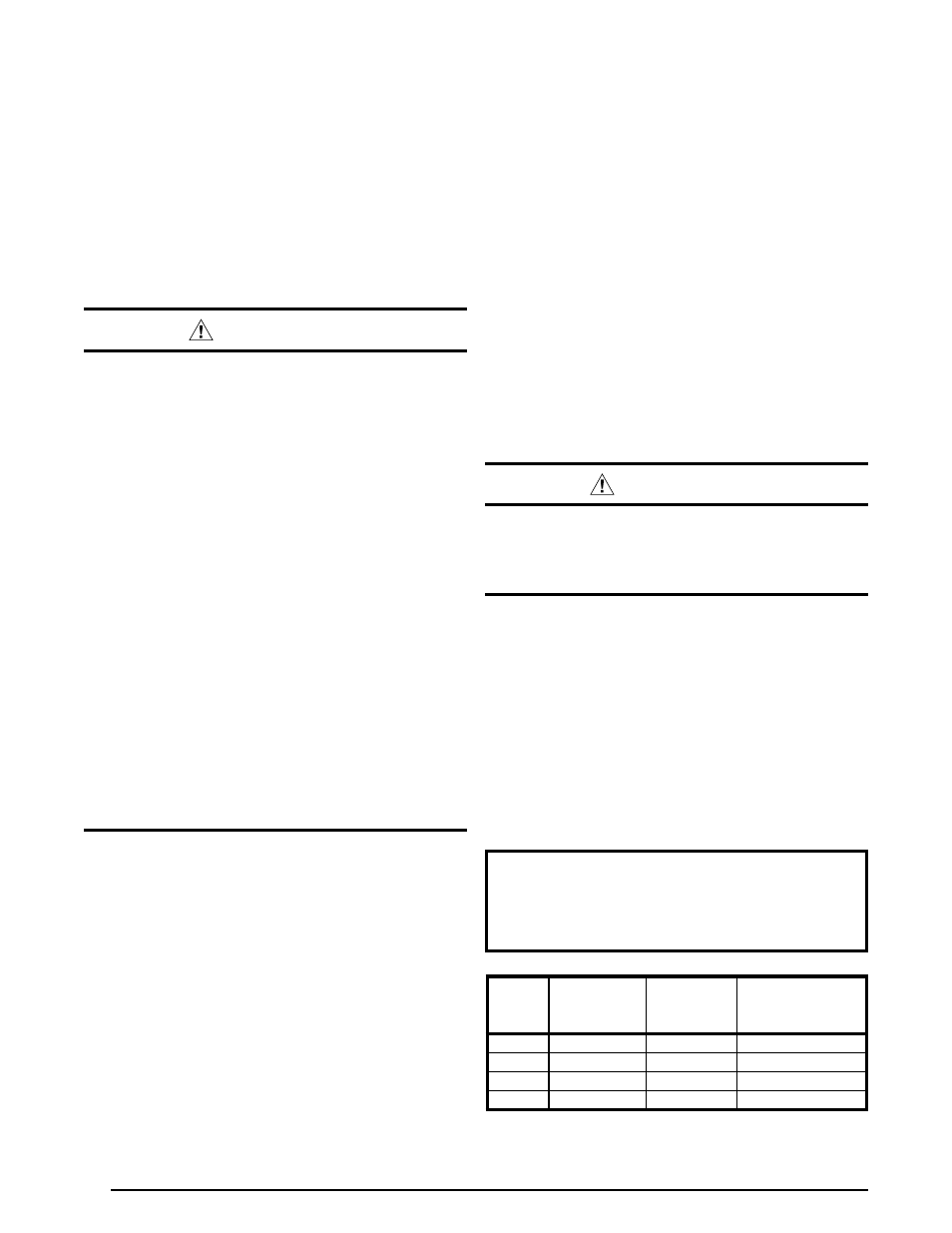
Table 1. Air Filter Requirements
Nominal
Cooling
(Tons)
Approximate
Air Flow
Range (CFM)
Approximate
Filter Area
(Sq. In.)*
Recommended
Filter Size
(In. x In.)
2
700 - 900
450
20 x 25
3
1,000 - 1,300
625
25 x 25
4
1,500 - 1,900
915
18 x 25 (2 required)
5
1,600 - 2,000
975
20 x 25 (2 required)
* Based on velocity of 300 ft/min for disposable filters.
• The unit installation shall avoid areas where condensate
drainage may cause problems by dropping on planters
or patios, etc. Also verify exhaust gases will not
impinge on windows or building surfaces, which may
be compromised or damaged by condensation.
• Do not install the unit such that exhaust from the vent
termination is directed into window wells, stairwells,
under decks, or in alcoves or similarly recessed areas.
The vent termination must not be located above any
public walkways.