Component functions, Troubleshooting – Reznor R6GF Unit Installation Manual User Manual
Page 23
23
COMPONENT FUNCTIONS
Comfort Alert™ Diagnostics -The Comfort Alert
diagnostics module troubleshoots heat pump and air
conditioning system failures and accurately detects the
cause of electrical and system related failures without
any sensors. A flashing LED indicator communicates the
ALERT code to quickly direct the technician to the root
cause of a problem.
Flame Roll-Out Control - The flame roll-out control acts to
verify that the burner flame is being drawn into the heat
exchanger tubes. If the burner flame is not being drawn
into the heat exchanger tubes, the roll-out control will
open within several seconds and the integrated control
diagnostic light will flash one time. If the limit opens, the
integrated control diagnostic will flash one time. The
circulating air blower will continue to operate while the
flame roll-out control is open.
Flame Sensor - The flame sensor acts to prove that flame
has carried over from the ignitor to the right-most burner. If
no flame is sensed, the unit will be shut down automatically.
Dual Pressure Switch - The dual pressure switch verifies
that the inducer motor is drawing the combustion gases
through the heat exchanger tubes and venting the
gases through the vent system for both high and low fire
conditions.
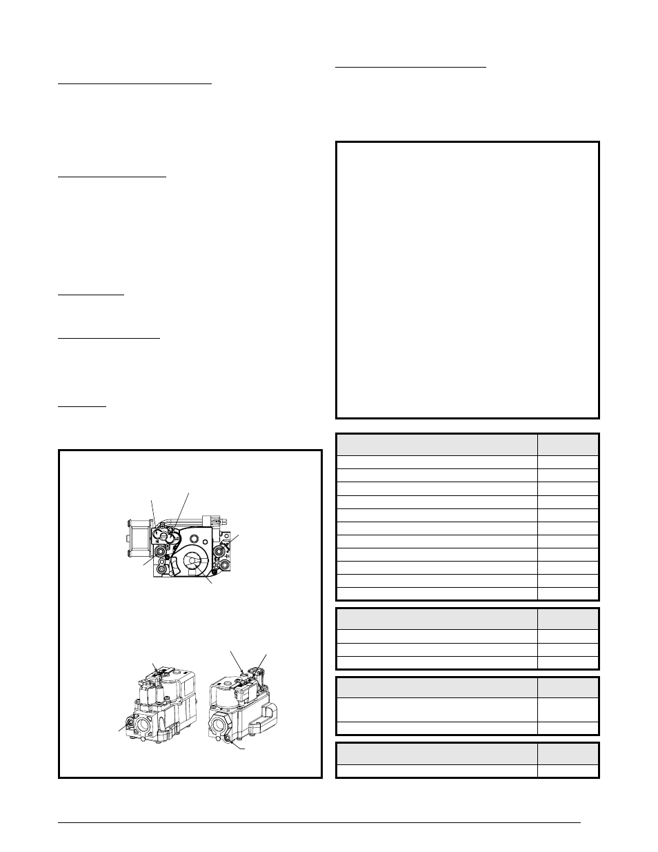
Gas Valve - The gas valve controls the flow of gas to the
burners in both low and high fire. When the gas valve is
energized it automatically opens and regulates the gas
pressure in the manifold. See Figure 8 below.
TROUbLESHOOTING
If the unit does not operate in the cooling mode, check
the following:
• The thermostat is operating properly
• Electrical power to the unit is turned on
• The filters are not dirty
• The service doors are in place
• The 5 amp fuse is operational
If the unit does not operate in the heating mode, check
the following:
• The thermostat is operating properly
• Electrical power to the unit is turned on
• The filters are not dirty
• The gas is turned on and the manual shut-off valve
is open
• The service doors are in place
• The flame roll-out control is closed
• The diagnostic codes listed in Table 7 or on the
wiring diagrams (Figures 11 or 12, pages 29 - 30).
• The 5 amp fuse is operational
Table 7. Ignition / Blower Control Diagnostic Codes
SYSTEM STATUS - IGNITION
LED STATUS
(RED)
Power On (Normal Operation)
ON
High Limit Circuit Open
1 Flash
Pressure Switch Open with Inducer On
2 Flashes
Pressure Switch Closed with Inducer Off
3 Flashes
Failed Ignition (5 attempts) - Control in 1 Hour Lockout
4 Flashes
208-230 Volt Polarity Issue
5 Flashes
Excess High limit trips (5) within one call for heat
6 Flashes
Excess pressure switch cycles (5) within one call for heat
7 Flashes
Excess flame dropouts (5) within one call for heat
8 Flashes
Not Used
9 Flashes
Flame present with gas valve Off
10 Flashes
SYSTEM STATUS - 2nd STAGE HEAT DEMAND
LED STATUS
(GREEN)
No demand for 2nd stage heat
OFF
2nd stage heat demand (Normal operation)
ON
2nd stage heat demand, high pressure switch not closed
Flashing
SYSTEM STATUS - HI/LO DEHUMIDIFY
(Cooling Mode only)
LED STATUS
(GREEN)
Factory jumper wire “R” to “DEHUM” in place or “Close
on Fall” humidistat (Low humidity) - Closed
ON
Humidistat open (High Humidity) Low Speed Blower call
OFF
SYSTEM STATUS - CFM
LED STATUS
(YELLOW)
NOT USED
OFF
IN
ON
OFF
Inlet
Pressure
Tap
Inlet
Pressure
Tap
Manifold
pressure
Tap
Manifold
pressure
Tap
2-STAGE GAS VALVES
Model VR8205Q2381
Model VR9205Q1028
ON / OFF
Knob
ON / OFF
Switch
HI Input
Adjusting Screw
Lo Input
Adjusting Screw
HI Input
Adjusting
Screw
Lo Input
Adjusting
Screw
Figure 8. HI & LO Input Adjusting Screws
Over-Temperature Limit Control - The over-temperature
limit control prevents the air temperature leaving the unit
from exceeding the maximum outlet air temperature. If the
limit opens, the integrated control diagnostic will flash one
time. The circulating air blower will continue to operate
while the over-temperature limit control is open.