Warning, Caution, Refrigerant charging – Reznor R6GF Unit Installation Manual User Manual
Page 19: Operating sequence, Heating mode
19
Refrigerant Charging
WARNING:
These units are shipped fully charged with
R-410A refrigerant and ready for installation.
When a system is installed according to these
instructions, no refrigerant charging is required.
If repairs make it necessary for evacuation and
charging, it should only be done by qualified,
trained personnel thoroughly familiar with this
equipment. Some local codes require licensed
installation/service personnel to service this
type of equipment. Under no circumstances
should the owner attempt to install and/or
service this equipment. Failure to comply with
this warning could result in property damage,
personal injury, or death.
CAUTION:
This unit uses R-410A refrigerant. DO NOT use
any other refrigerant in this unit. Use of another
refrigerant will damage the unit.
The system refrigerant charge can be checked and
adjusted through the service ports provided at the front
panel. Use only gauge lines which have a Schrader
depression device present to actuate the valve. Refrigerant
charging must be done by qualified personnel familiar with
safe and environmentally responsible refrigerant handling
procedures. Refer to the application notes and charging
charts on pages 33-35
Charging an R-410A unit in AC mode at
outdoor temperatures above 65F.
1. With the system operating at steady-state, measure the
liquid refrigerant pressure in psig at the service valve.
2. Measure the liquid refrigerant temperature in Fahrenheit
at the outlet of the condensor coil.
3. For the temperature measured, determine the required
liquid refrigerant pressure from the appropriate charging
charts in Figures 14 - 17 (pages 34 - 35).
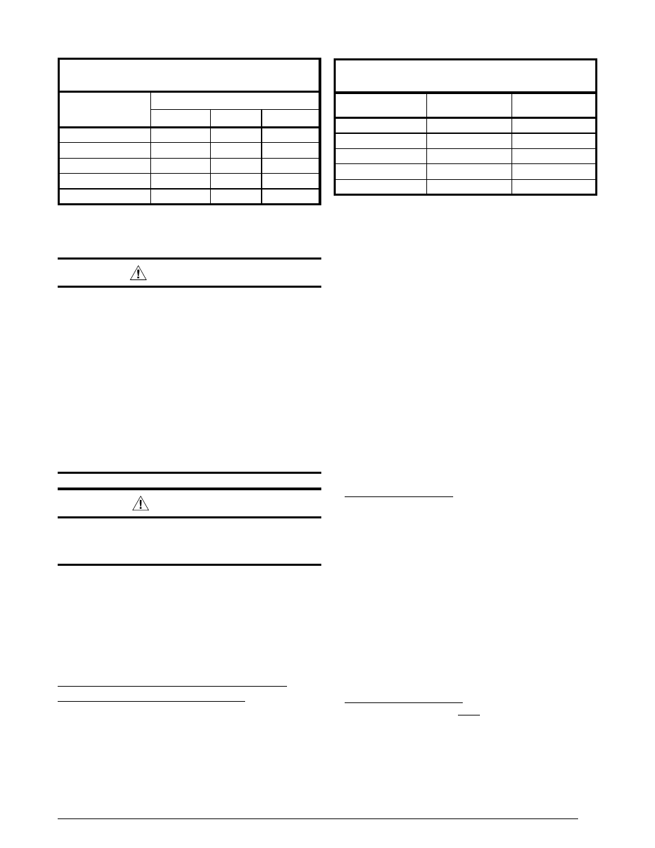
Table 5. Manifold Pressure (in W.C.) for Natural Gas
Manifold Pressure (in W.C.) for
Natural Gas Installations
Altitude above
sea level
Heating Value Btu/cu. ft.
800 to 899
900 to 999
1,000 to 1,100
zero to 1,999 FT
3.5
3.5
3.5
2,000 to 4,999 FT
3.5
3.5
3.5
5,000 to 5,999 FT
3.5
3.5
3.0
6,000 to 7,999 FT
3.5
3.2
2.8
8,000 to 10,000 FT
3.0
2.8
2.5
Table 6. Manifold Pressure (in W.C.) for LP Gas
Manifold Pressure (in W.C.) and Orifice Sizes
for LP/Propane Gas Installations
Altitude above
sea level
Manifold
Pressure
Orifice
Size
zero to 1,999 FT
10.0
55
2,000 to 4,999 FT
8.5
55
5,000 to 5,999 FT
10.0
56
6,000 to 7,999 FT
9.0
56
8,000 to 10,000 FT
8.5
56
NOTE: Manifold pressure based on sea level LP heating value
of 2,500 Btu/cu. ft.
3
4. If the pressure measured in step 1 is greater than the
required liquid refrigerant pressure determined in step
3, then there is too much charge in the system. Remove
refrigerant and repeat steps 1 through 3 until the system
is correctly charged.
5. If the pressure measured in step 1 is less than the
required liquid refrigerant pressure determined in step
3, then there is too little charge in the system. Add
refrigerant and repeat steps 1 through 3 until the system
is correctly charged.
OPERATING SEQUENCE
The operating sequences for the heating, cooling, and
fan modes are described below. Refer to the field and
furnace wiring diagrams (Figures 12 or 13, pages 29 - 30).
Heating Mode
1. On a call for 1st stage heat, the thermostat closes and
applies 24 VAC to terminal W on the control board.
2. Safety Circuit Proving - The control board verifies
continuity through the 24VAC limit control circuit. If the
high temperature limit switch and flame roll-out switch
are closed and both the high and low vent pressure
switches are open, the control board will then begin
pressure switch proving. If an open limit is detected, the
control board will energize the indoor blower motor and
operate it continuously while the limit switch circuit is
open. All other system functions will be inoperable until
the limit circuit closes. While the limit circuit is open, the
control will flash 1 on the red LED.
3. The furnace control checks for continuity (24 VAC)
across the pressure switch. If the pressure switch is
closed, the heat mode sequence will not continue. If it
remains closed for 10 seconds, the red LED will flash
3 times repetitively until the fault condition clears.
4. Pressure Switch Proving - The control energizes the
induced draft motor on High speed and waits for the
low pressure vent switch to close. If the low pressure
switch does not close within 60 seconds, the control
will flash 2 on the red LED. If the low pressure switch
does not close before 60 seconds expires, the control
will de-energize the inducer for 60 minutes and continue
to flash 2 during the 60 minute inducer off period. After