Line voltage, Thermostat / low voltage connections, Heat / cool thermostat – Reznor R6GF Unit Installation Manual User Manual
Page 11
11
√
Verify factory wiring is in accordance with the unit wiring
diagram (Figures 12 & 13, pages 29 - 30). Verify the
connections didn’t loosen during shipping or installation.
Line Voltage
• The line voltage to the unit should be supplied from a
dedicated branch circuit containing the correct fuse or
circuit breaker for the unit.
•
An electrical disconnect must be located within
sight of and readily accessible to the unit
. This
switch shall be capable of electrically de-energizing the
outdoor unit. See unit data label for proper incoming field
wiring. Any other wiring methods must be acceptable
to authority having jurisdiction.
• Use only copper wire for the line voltage power supply
to this unit (Table 3, page 12). Use proper code agency
listed conduit and a conduit connector for connecting
the supply wires to the unit. Use of rain tight conduit is
recommended.
• Provide power supply for the unit in accordance with
the unit wiring diagram and the unit rating plate.
• Overcurrent protection must be provided at the branch
circuit distribution panel and sized as shown on the unit
rating label and according to applicable local codes.
See the unit rating plate for maximum circuit ampacity
and maximum overcurrent protection limits.
• A wiring diagram is located on the inside cover of the
control access panel of the outdoor unit. The installer
should become familiar with the wiring diagram before
making any electrical connections to the outdoor unit.
See Figures 12 & 13.
• If any of the original wires supplied with the unit must
be replaced, they must be replaced with material of
the same gauge and temperature rating.
• Units are shipped from the factory wired for 240 volt
transformer operation. For 208V operation, remove the
lead from the transformer terminal marked 240V and
connect it to the terminal marked 208V.
• Connect the line-voltage leads to the terminals on the
contactor inside the control compartment.
Thermostat / Low Voltage Connections
• These Gas / Electric units are designed to operate
with a 24 VAC Class II control circuit. The control circuit
wiring must comply with the current provisions of the
NEC (ANSI/NFPA 70) and with applicable local codes
having jurisdiction. Thermostat connections should be
made in accordance with the instructions supplied with
the thermostat and the indoor equipment.
• These units use a special 2 speed compressor to
achieve a high level of efficiency in a compact frame.
A 2 stage cooling / 2 stage heating 24V thermostat
should be used with this unit. See Figure 10 (page 28).
• The low voltage wires must be properly connected
to the units low voltage terminal block. Route 24V
control wires through the gas furnace side of the unit.
Recommended wire gauge and wire lengths for typical
thermostat connections are listed in Table 4 (page 12).
• The thermostat should be mounted about 5 feet
above the floor on an inside wall. DO NOT install the
thermostat on an outside wall or any other location
where its operation may be adversely affected by radiant
heat from fireplaces, sunlight, or lighting fixtures, and
convective heat from warm air registers or electrical
appliances. Refer to the thermostat manufacturer’s
instruction sheet for detailed mounting information.
Heat / Cool Thermostat
2 Stage Heat / 2 Stage Cool Thermostat (Recommended):
For highest efficiency a 2 Stage Heating/Cooling thermostat
is recommended for this product. A 2 Stage Cool thermostat
is required for control of the special 2 speed compressor.
A 2 Stage Heat thermostat will allow the gas heat to
operate at a more efficient low heat condition until there
is a demand for higher heat output to the conditioned
space. See Figure 11A (page 28).
Single Stage Heat / 2 Stage Cool Thermostat (Optional):
A 2 Stage Cool thermostat is required for control of
the special 2 speed compressor. A single stage Heat
thermostat can be used in conjunction with the automatic
heat staging jumper on the ignition control board. The heat
staging function will automatically move the unit into high
heat operation at the time interval selected:
None = Low heat operation only, 5 = 5 minute delay from
low to high heat mode, and 10 = 10 minute delay from low
to high heat mode. See Figure 11B (page 28).
Connect the Red, Yellow, Green, Blue, White, and Brown
(optional) low voltage thermostat wires to terminals R,
Y1 (1st Stage Cool), G, Y2 (2nd Stage Cool), W1 (1st
Stage Heat), & W2 (2nd Stage Heat-optional) on both the
thermostat sub-base and unit low voltage terminal board.
The C terminal (Black wire), is the 24V common wire
required on some thermostat models. See Figure 12 or 13.
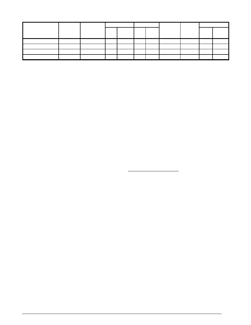
Table 2. Electrical Data
Model
Number
Maximum
Heating
Input
Nominal
Electrical
Supply
Voltage Range
Compressor
Fan
Motor
FLA
Indoor
blower
FLA
Single Circuit
Min
Max
RLA
LRA
MCA
MOP
X24K080XA
80,000
208-230/60/1
187
253
11.7
58.3
0.91
4.3
20.3
30.0
X36K100XA
100,000
208-230/60/1
187
253
15.3
83.0
1.46
4.3
25.4
40.0
X48K120XA
120,000
208-230/60/1
187
253
21.2
104.0
1.46
9.1
37.5
50.0
X60K120XA
120,000
208-230/60/1
187
253
28.8
152.9
1.46
9.1
47.0
70.0
Note: FLA = Full Load Amps; LRA = Lock Rotor amps; RLA = Rated Load Amps.