Thermostat demand wiring, L terminal wiring, Dc sol connection – Reznor R6GF Unit Installation Manual User Manual
Page 13: Optional humidistat, Optional comfort alert, Diagnostics module, 24 vac power wiring
13
due to safety controls, defrost boards, or other control
boards which could lead to nuisance alerts.
Thermostat Demand Wiring
The Comfort Alert module requires a two stage thermostat
to operate properly. The Y2 thermostat wire entering the
outdoor unit should be connected to the Y2 input on the
unit terminal strip.
While the compressor is running, Comfort Alert will provide
power to the second stage cooling solenoid inside the
compressor after Y2 has been energized for 5 seconds.
When the compressor is not running, Comfort Alert will
not power the solenoid, regardless of the state of Y2. If
Alert codes 1 or 9 appear while the compressor is running,
Comfort Alert will turn off the solenoid to prevent solenoid
damage from overheating conditions.
L Terminal Wiring
White-Rodgers Compatible Thermostats - The L
connection is used to communicate Comfort Alert codes
to compatible White-Rodgers thermostats. The L terminal
of these thermostats should be connected to the Comfort
Alert L terminal. See unit wiring diagram label included
on the unit or in these instructions for correct field wiring
connections.
NOTE: On some White-Rodgers combatible thermostats,
an icon on the thermostat display will flash at the same rate
as the Comfort Alert yellow Alert LED. An advanced option
on these thermostats is to lock out the compressor when
certain Alert codes are detected in indicating impending
compressor damage. Refer to White-Rodgers thermostat
manuals for more information.
Standard Non-Compatible Thermostats
– The
L
connection on non-compatible type thermostats are used
for heat pump defrost control board fault monitoring. The L
terminal of these thermostats should be connected directly
to the defrost control board L terminal. See the wiring
diagram label or the heat pump installation instructions
for correct field wiring connections.
DC SOL Connection
The two pin DC SOL connector provides a connection to
the Copeland UltraTech second stage compressor solenoid
(Figure 13, page 28). This 24VDC solenoid is internal to
Optional Humidistat
An optional humidistat may be installed in the return
air duct for humidity control (when needed), maximum
system capacity and energy efficiency. The humidistat
senses when humidity in the return air stream is above
a preset level and sends a signal to the motor to reduce
airflow. This allows more moisture to be removed until
the humidity level drops. NOTE: The indoor blower motor
of this packaged unit is pre-programmed for humidistat
operation. Remove the Red jumper wire between the R
and DEHUM terminals on the ignition control board.
If installing a humidistat, install it in the return air duct
as directed in the installation instructions included with
the kit. Wire the humidistat through the low-voltage wire
entrance in the packaged unit to the screw terminals
marked R & DEHUM.
Wire the humidistat to open on
rise in humidity.
When the HI/LO Dehumidify Green LED status light is
ON, it signals Low Humidity and keeps 24V supplied to
the motor for normal airflow requirements. If the humidity
level of the conditioned space increases the humidistat
will open. Loss of the 24V signal to the indoor blower
motor allows the motor to reduce to approximately 75%
of normal airflow selected until the humidity level drops.
The Green LED is OFF during high humidity conditions.
See Figure 11B (page 28).
Check all factory wiring to the units wiring diagram. Inspect
the factory wiring connections to be sure none loosened
during shipping or installation.
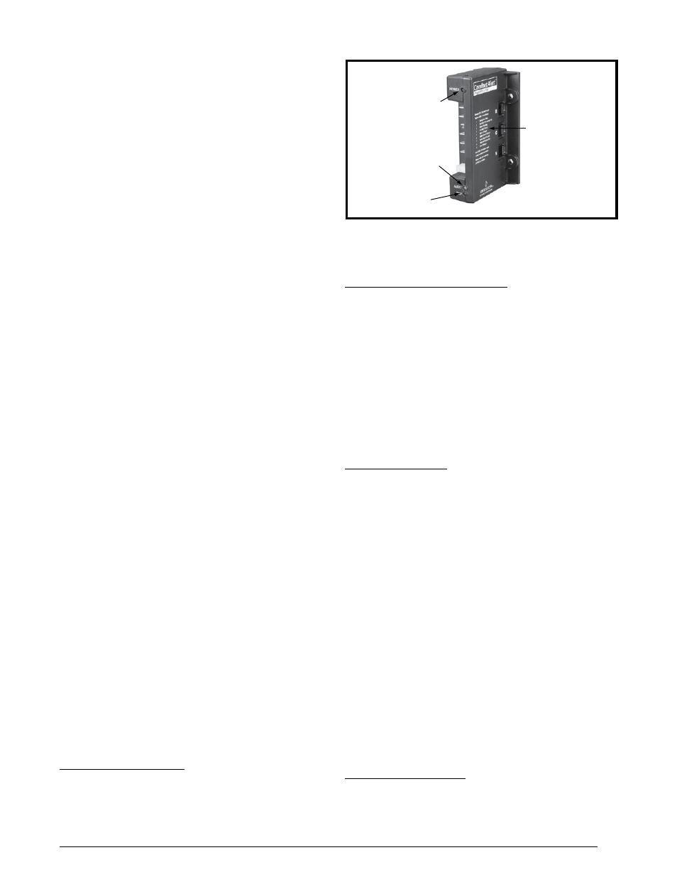
Optional Comfort Alert
TM
Diagnostics
Module
The Comfort Alert
TM
Diagnostics Module is a breakthrough
innovation for troubleshooting heat pump and air
conditioning system failures. The module installs easily in
the electrical box of the outdoor unit near the compressor
contactor. By monitoring and analyzing data from the
Copeland scroll compressor and the thermostat demand,
the module can accurately detect the cause of electrical
and system related failures without any sensors. A
flashing LED indicator communicates the ALERT code
and a diagnostic key is also imprinted on the side of the
module to quickly direct the technician to the root cause
of a problem. See Figure 6.
NOTE: This module does not provide safety protection!
The Comfort Alert
TM
Diagnostics Module is a monitoring
device and cannot control or shut down other devices.
24 VAC Power Wiring
The Comfort Alert
TM
module requires a constant nominal
24 VAC power supply. The module should be powered by
an R & C that doesn’t have the potential for loss of power
nominal rise based on the furnace’s nominal efficiency
and firing input. Follow across the table row to find the
tap setting and nominal air-flow. Verify the selected rise is
within the specification shown on the furnace rating label.
Figure 6. Comfort Alert
TM
Diagnostics Module
POWER LED
(Green)
TRIP LED
(Red)
ALERT LED
(Yellow)
Diagnostics
Key