Electrical information, Dehum – Reznor R6GF Unit Installation Manual User Manual
Page 28
28
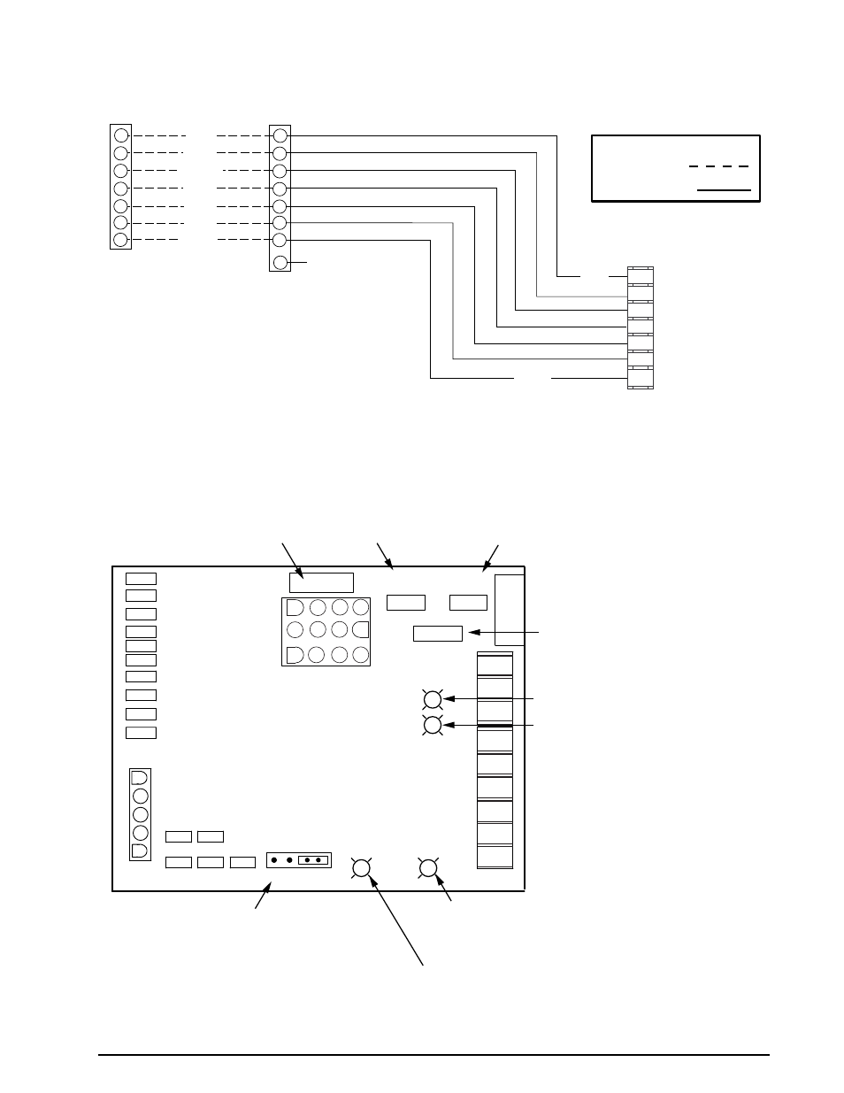
ELECTRICAL INFORMATION
Figure 11A. Two Stage Heating / Two Stage Cooling Configuration
Legend
Field Wiring
Factory Wiring:
TERMINAL STRIP
THERMOSTAT
R
Y1
G
Y2
C
W2
W1
R
Y1
G
Y2
C
W2
W1
RED
YELLOW
GREEN
BLACK
BLUE
WHITE
BROWN
R
C
Y
G
W1
Y2
W2
BLUE
BROWN
S2 Cool
S2 Heat
24VAC Com
S1 Heat
Fan
S1 Cool
24VAC
L
Comfort Alert Module
(Select Models Only)
See Note
NOTE:
For use with White Rogers compatible thermostats only.
Refer to the thermostat manual for detailed installation and
programming instructions.
W1
W2
C
R
G
Y
Y2
0
DEHUM
P2
1
5
HUM
LINE
XMFR
CONT
EAC
COOL
PARK1
PARK2
HI-HEAT
LO-HEAT
NEUTRALS
AUTO
HEAT STAGE
10 5 NONE
HOT SURFACE IGNITION
VARIABLE SPEED BLOWER
CONTROL BOARD
COOL
A B C D
HEAT
A B C D
ADJUST
NORM
(+)
(-)
TEST
Low Voltage
Control Circuit
5 Amp Fuse
Heating Speed
Selector (Table 11)
Cooling Speed
Selector (Table 10)
CFM Adjustment Selector
Cooling Speed Only(Table 10)
LED (Yellow) - Not Used
LED (Green) - Dehumidification
(Cooling Mode Only) See Page 13
& Troubleshooting Page 23
LED (Red) - Ignition
(See Operating Sequence
& Troubleshooting)
LED (Green) - High Heat Demand
(See Troubleshooting)
Automatic Heat Staging
(Used with Single Stage
Heating Thermostat)
Figure 11B. Two-Stage, Hot Surface Ignition & Blower Control Board
- UDAP Unit Installation Manual (40 pages)
- UDBP Unit Installation Manual (44 pages)
- UEAS Unit Installation Manual (44 pages)
- VPS Unit Installation Manual (44 pages)
- VPT Unit Installation Manual (40 pages)
- VCS Unit Installation Manual (48 pages)
- CAUA Unit Installation Manual (44 pages)
- EEDU Unit Installation Manual (32 pages)
- LDAP Unit Installation Manual (44 pages)
- MASA Unit Installation Manual (40 pages)
- RDF Unit Installation Manual (28 pages)
- RPB Unit Installation Manual (40 pages)
- SC Duct Furnace Unit Installation Manual (40 pages)
- SSCBL Unit Installation Manual (60 pages)
- X Unit Installation Manual (32 pages)
- ZQYRA Unit Installation Manual (72 pages)
- ADF Unit Installation Manual (28 pages)
- F Unit Installation Manual (40 pages)
- PDH (Indoor PreevA) Unit Installation Manual (72 pages)
- MAPSIII Unit Installation Manual (76 pages)
- RDH (Outdoor PreevA) Unit Installation Manual (68 pages)
- RP (Outdoor Duct Furnaces) Unit Installation Manual (32 pages)
- YDHA Unit Installation Manual (76 pages)
- OH Unit Installation Manual (28 pages)
- RBL (Cabinet Blower) Unit Installation Manual (12 pages)
- REC (Evaporative Cooling) Unit Installation Manual (12 pages)
- RIHN Unit Installation Manual (20 pages)
- UDAP Option - Installation - Power Venting (12 pages)
- UDAS Option - Installation - Separated Combustion Venting (16 pages)
- WS Unit Installation Manual (15 pages)
- EBHB Option - Installation - Thermostat Kit (2 pages)
- EFMA Unit Installation Manual (27 pages)
- EWHB Unit Installation Manual (9 pages)
- EXUB Unit Installation Manual (16 pages)
- XAWS Unit Installation Manual (12 pages)
- XAWU Unit Installation Manual (12 pages)
- XBWU Unit Installation Manual (12 pages)
- MAPS III Option - Installation - Energy Recovery Module Installation (12 pages)
- UDAP in sizes 30 through 125 Option - Installation - Ceiling Suspension Kit (2 pages)
- UEAS Option - Installation - Downturn Nozzles - V3 (4 pages)
- UDBP Option - Installation - Polytube Adapter Instructions (4 pages)
- UDBS Option - Installation - Vertical Louvers - V3 Series (2 pages)
- B Option - Installation - Blower/Filter Cabinet (4 pages)
- PDH with 1-stage gas control or 2-stage gas control Gas Conversion Kit Instructions (8 pages)
- VP series infrared heaters High altitude conversion instructions (12 pages)