Warning – Reznor B5SM Unit Installation Manual User Manual
Page 2
2
IMPortAnt sAFEtY InForMAtIon
Please read all instructions before servicing this equipment.
Pay attention to all safety warnings and any other special
notes highlighted in the manual. Safety markings are
used frequently throughout this manual to designate a
degree or level of seriousness and should not be ignored.
WArnInG indicates a potentially hazardous situation that
if not avoided, could result in personal injury or death.
CAutIon indicates a potentially hazardous situation that
if not avoided, may result in minor or moderate injury or
property damage.
WArnInG:
ELECtrICAL sHoCK, FIrE or EXPLosIon
HAZArD
Failure to follow safety warnings exactly could
result in serious injury or property damage.
Improper servicing could result in dangerous
operation, serious injury, death or property
damage.
• Before servicing, disconnect all electrical
power to the indoor blower.
• When servicing controls, label all wires prior
to disconnecting. reconnect wires correctly.
• Verify proper operation after servicing.
IMPortAnt sAFEtY InForMAtIon .......................2
GEnErAL InForMAtIon ..........................................3
Before You Install this Unit .........................................3
Locating the Air Handler ............................................4
Field Connections for Electrical Power Supply ..........4
Air Ducts ....................................................................4
Unconditioned Spaces ...........................................4
Acoustical Duct Work .............................................4
AIr HAnDLEr InstALLAtIon ..................................4
Packaging Removal ...................................................4
Minimum Clearance Requirements ...........................4
Horizontal Mounting Applications ..............................4
Vertical Mounting Applications ..................................4
Condensate Drain ....................................................4
Connecting Refrigerant Tubing ..................................5
Filter Requirements ..................................................5
ELECtrICAL WIrInG .................................................6
Pre - Electrical Checklist ...........................................6
Line Voltage ...............................................................6
Thermostat Connections ...........................................7
Electrical Wiring with a Duct Heater ..........................7
Unbalanced 3-Phase Supply Voltage ........................7
Grounding..................................................................8
stArtuP & ADjustMEnts .....................................8
Pre - Start Checklist ..................................................8
Blower Speed Adjustment .........................................8
Motor Sheave Adjustment .........................................8
V-Belt Alignment & Tensioning ..................................8
Blower Rotation .........................................................8
unIt MAIntEnAnCE ..................................................9
FIGurEs & tABLEs .................................................10
Figure 4. Physical Dimensions - Horizontal ..........10
Figure 5. Physical Dimensions - Vertical ..............11
B5SM 090 & 120 Blower Performance Tables .........12
Table 3- Alternate Accesory Blower Drives ..........12
Table 4- Pressure Drop Across Filters .................12
Table 5 - Single Phase - 7.5 Ton Models ..............13
Table 6 - Single Phase - 10 Ton Models ...............14
Table 7 - Three Phase - 7.5 Ton Models ...............15
Table 8 - Three Phase - 10 Ton Models ................16
Electrical Information ...............................................17
Figure 7. B5SM Wiring Diagram ...........................17
Figure 8. Motor Wiring Diagram -3 Phase ............17
Figure 9. Air conditioner T-stat Connections .........18
Figure 10. Heat pump T-stat Connections ............19
Maintenance Schedule ............................................20
Table 9. Maintenance Schedule ...........................20
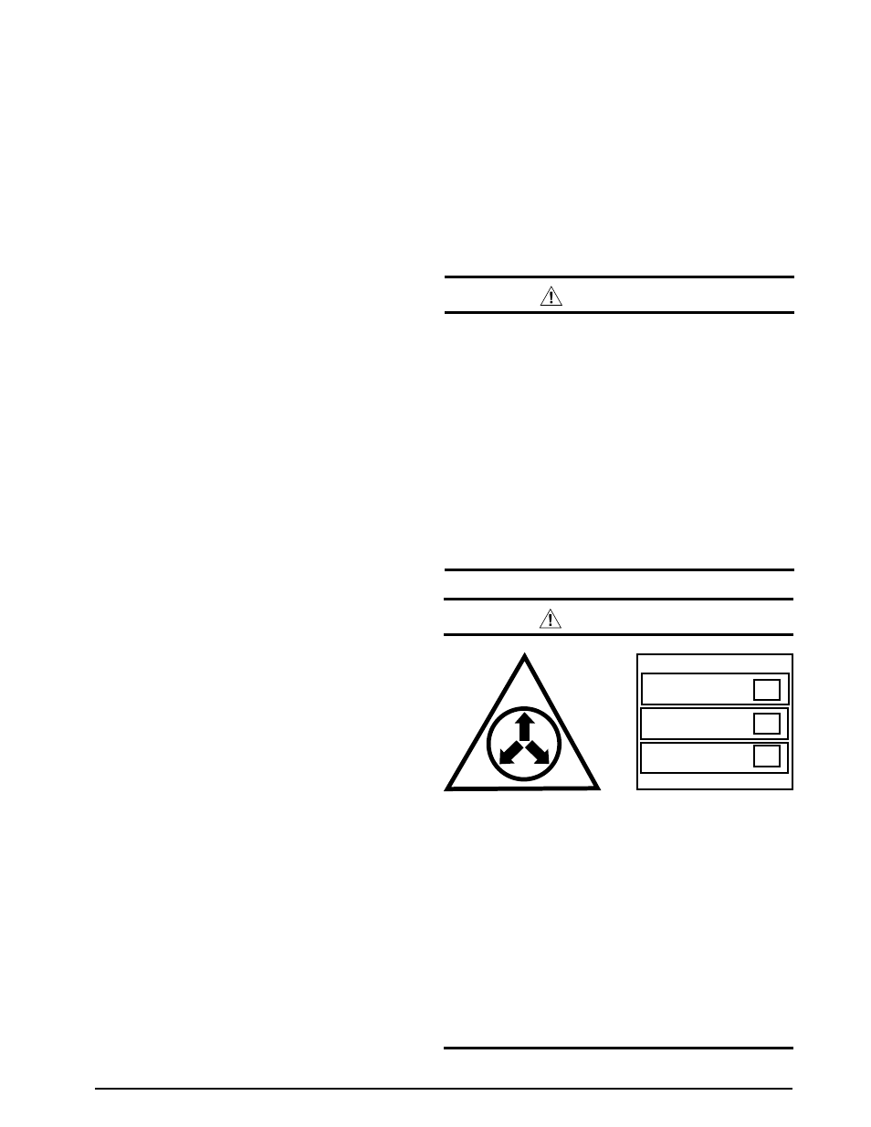
WArnInG:
Evaporator coils are shipped from the factory
with a nitrogen charge. use caution when
preparing coils for field connections. If repairs
make it necessary for evacuation and charging,
it should only be attempted by qualified,
trained personnel thoroughly familiar with this
equipment. some local codes require licensed
installation service personnel to service this
type of equipment. under no circumstances
should the equipment owner attempt to install
and/or service this equipment. Failure to comply
with this warning could result in equipment
damage, personal injury, or death.
NITROGEN
HEALTH
FLAMMABILITY
REACTIVITY
0 Minimal Hazard
1 Slight Hazard
1
0
0