Wiring diagram, Electrical configurations, Electrical information – Reznor B5SM Unit Installation Manual User Manual
Page 17: Figure 8. motor wiring diagram (3-phase only), Three phase, Single phase
17
THREE PHASE
G
C
W2
W1
O/B
Y
R
L3
L2
L1
G
L1
L2
T1
T2
L3
T3
FREEZESTAT
Y
Tstat
BLACK
BROWN
L1
L2
L3
G
FIELD SUPPLY CONNECTIONS
SEE
NOTE 3
SINGLE PHASE
G
C
W2
W1
O/B
Y
R
L2
L1
G
L1
L2
T1
T2
FREEZESTAT
Y
Tstat
BLACK
BROWN
L1
L2
G
FIELD SUPPLY CONNECTIONS
SEE
NOTE 3
Electrical Configurations
1. Three phase units are factory wired for
460V/60Hz operation.
2. To reverse motor rotation, interchange
any two field wired line leads.
7111570
02/11
FIELD WIRING
LEGEND:
LOW VOLTAGE
WIRING DIAGRAM
B5SM Series
7.5/10T Air Handler Systems
GENERAL NOTES:
THREE PHASE ONLY NOTES:
1. Disconnect all power before servicing.
2. If wiring must be replaced, use only
105˚C copper wire of the same gauge.
3. For economizer application, refer to wiring
instructions in economizer installation
instructions for connection details.
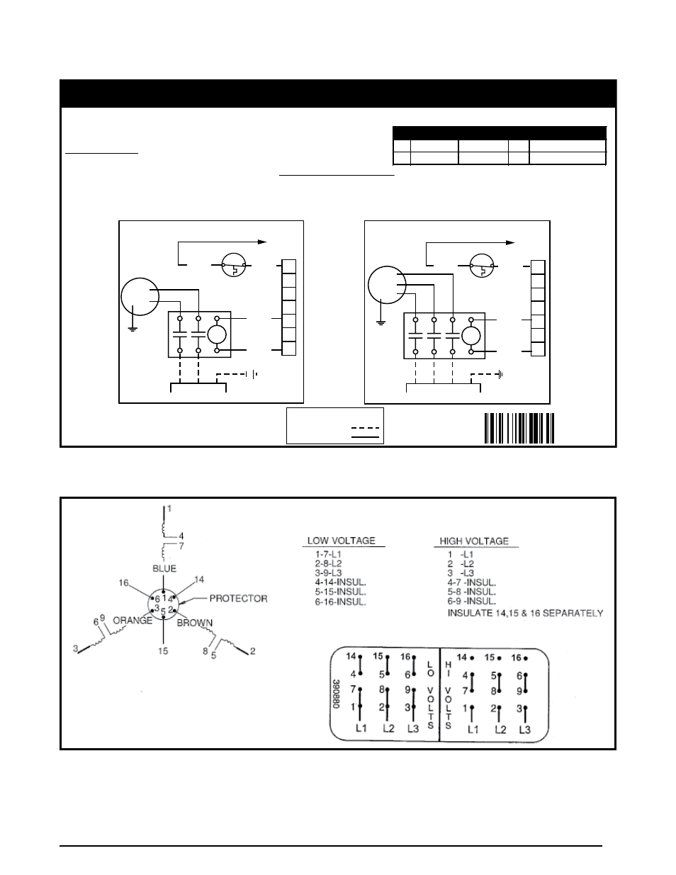
3. To reconfigure 3Ø units for operation
at 208-230V. Refer to motor wiring
diagram on the motor case or the unit
installation instructions.
Elec. Code
Freq./Phase
Voltages
J
60 Hz / 3Ø
208-230 / 460V
K
60 Hz / 1Ø
208-230
GREEN
BLACK
GREEN
BLACK
Figure 7. Wiring Diagram for single & three Phase units
ELECtrICAL InForMAtIon
Figure 8. Motor Wiring Diagram (3-Phase only)