Blower performance tables, Table legend – Reznor B5SM Unit Installation Manual User Manual
Page 12
12
Blower Performance tables
This equipment is equipped with a belt driven blower assembly in order to accommodate a large variety of duct
configurations and airflow selections. The blower has been factory inspected for proper alignment, operation and
rotational direction. For a more detailed explanation of belt driven blower drives and the operation of their components
please refer to any of the installation instructions listed below for the high static drive kits.
The factory standard drive installed in these units has been set to deliver 400 Cfm/ton at an External Static Pressure
(ESP) of 0.25-0.30 in-Wg. Consult Table 4 or the unit rating label for the proper air filter size, circulating airflow and
temperature rise for your unit. Tables 5-10 show the full blower curves of these drive configurations and can be utilized
to easily set the adjustable motor sheave for alternate configurations. Refer to the Legend below for a description
of the table information. After a sheave setting has been made, always inspect the blower amp draw to ensure that
it is less then the service factor amps listed on the motor. For systems that include a large number of accessories
or have very restrictive duct systems, alternate drive kits are available. Refer to Table 3 below for the applicable
kits. The full blower curves for the HSD kits can be found in the applicable kit installation instructions or in the unit
technical service literature.
3862
1159
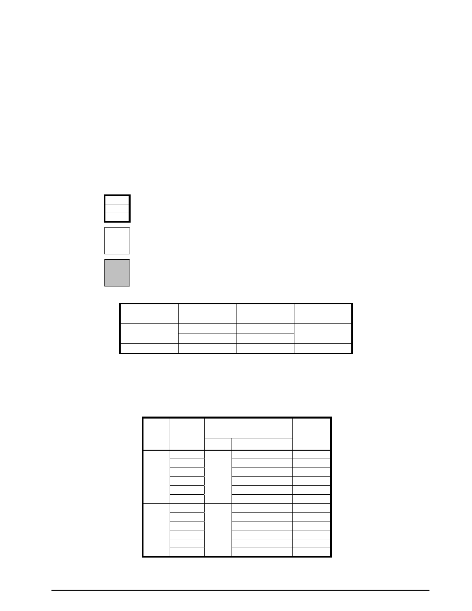
Indicates a recommended unit operational point
3.03
3493
Indicates an allowable setting that is not recommended for unit operation
†
† These operational points should be carefully examined by the installer for proper unit setup and heater operation if used.
1017
2.07
Indicates a setting that is not permitted for unit operation
table
Legend
table 3. B5sM series Alternate Accessory Blower Drives
unit Model #
E.s.P. range
(in-Wg)
Blower rpm
range
HsD
Kit
-090Ja
0.2 - 0.9
575 - 831
921428
0.3 - 1.2
610 - 898
-120Ja
0.1 - 1.2
727 - 971
921429
Refer to B5SM TSL or Accessory Kit Installation Instructions for actual blower charts
Model
B5sM
nominal
CFM
1” permanent Filters
(supplied)
Wet Coil
Correction
Δ P (in-Wg)
size
Δ P (in-Wg)
090
(J/K)a
2200
18 x 24
0.03
0.017
2600
0.04
0.019
3000
0.05
0.021
3400
0.07
0.023
3800
0.08
0.025
4200
0.09
0.026
120
(J/K)a
3000
18 x 24
0.05
0.180
3400
0.07
0.202
3800
0.08
0.223
4200
0.09
0.245
4600
0.11
0.266
5000
0.13
0.287
table 4. Pressure Drop Across Filters