Reznor B Option - Power Venter Installation User Manual
Page 7
Form I-F/B-PV, P/N 97967R2, Page 7
Feed the line voltage wires (black
and white) through the 90°
con-
nector. Tighten the cover on the
connector being careful not to
punch a hole in the conduit.
Feed the four low voltage wires
(brown, yellow, blue, and orange)
through the straight box connec-
tor. Tighten the holding screw.
FIGURE 10 -
Conduit Placement
Conduit must not
interfere with fan
operation or contact
hot surfaces of the
flue collection box
or vent pipe.
3) Connect the Wires in the Venter Junction Box -- Using the twist-on wire
connectors provided and following the wiring diagram in
FIGURE 14, page 9,
make the six connections. Either replace the junction box cover now or after
you have tested the venter operation (Paragraph 9).
attached to the hole
closest to the front of the heater. Insert a red plastic anti-short bushing in the end of
the conduit.
WARNING: Do not omit the anti-short bushings.
6. Connect Power
Venter and Heater
Wiring
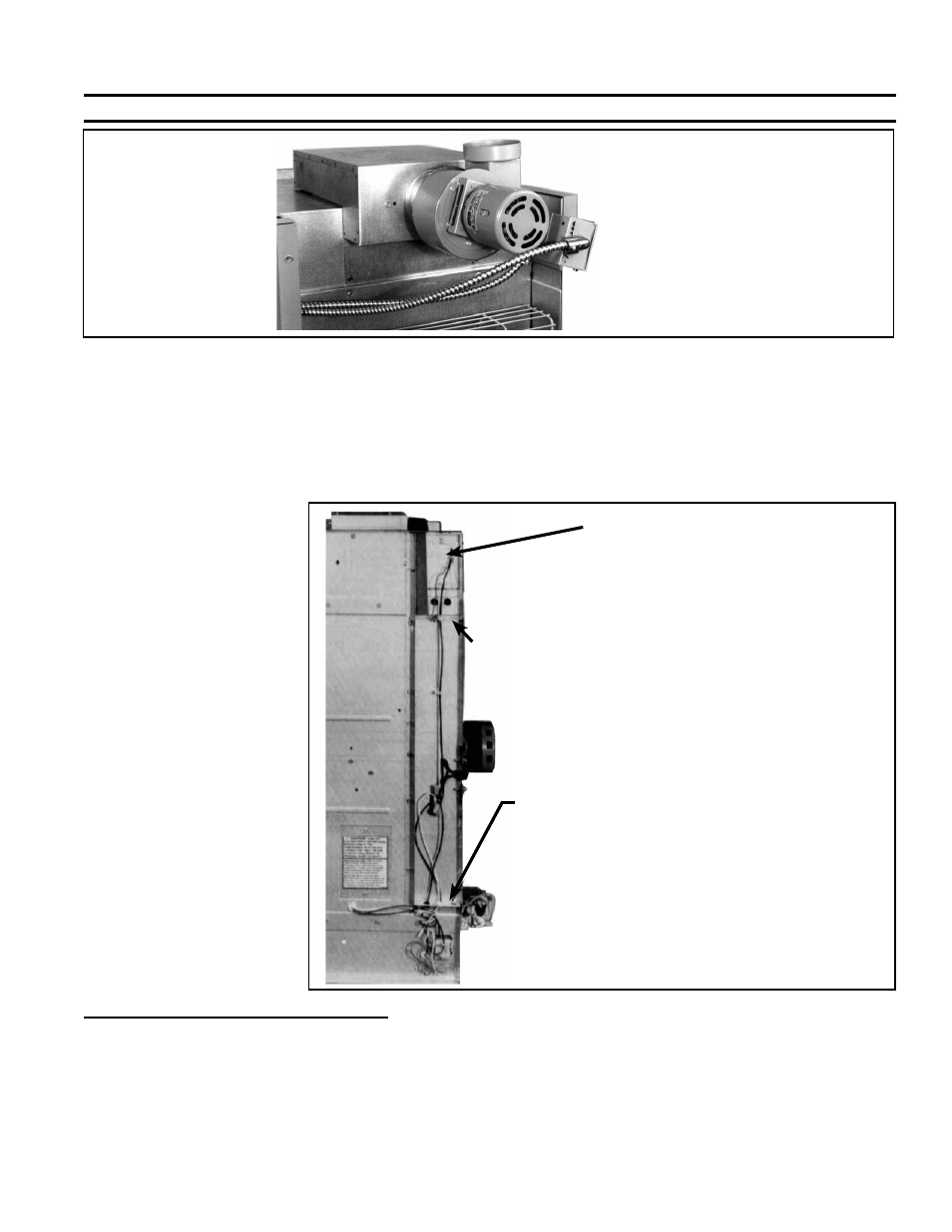
FIGURE 11 - Wiring
on the Inner Side
Panel of a Standard
Fan Model (without
the power venter
installed)
Either plastic cable holders or metal
partition (illustrated)
Heaters manufactured prior to 6/92 have two
horizontal metal partitions and require installation
of both the open/closed bushings in the kit. Heat-
ers manufactured beginning 6/92 have only an
upper metal partition and plastic cable holders in
the lower position. Only one of the open/closed
black bushings in the kit is used.
Upper
Metal
Partition
Electrical box for line voltage
connection.
If the unit has an optional unit-
mounted disconnect switch (Option
AI1), connect the supply wires to the
venter wires in series after the on/off
switch. When the switch is off, the
venter should not have power. (See
wiring diagram on page 9.)
If the outer side panel (left when facing the rear of the heater) has not been
removed, remove it to wire the heater for venter operation. See
FIGURE 11.
Line Voltage Wiring (black and white) - Connect the line voltage wires in the electrical supply box on the
inner side panel. Follow the wiring diagram in
FIGURE 14, page 9.
On a blower unit, use the two large (yellow) twist-on wire connectors in the option package to make the line
voltage connections.
On a fan unit equipped with an optional disconnect switch (Option AI1), the on/off switch in located at the
electrical supply box (See
FIGURE 7, page 6). Connect the black supply wire in series after the disconnect
switch. When the disconnect switch is off, power should be disconnected to the venter.