Horizontal vent terminal, Horizontal vent terminal clearances – Reznor B Option - Power Venter Installation User Manual
Page 11
Form I-F/B-PV, P/N 97967R2, Page 11
Instructions for attaching double-wall (Type B) vent pipe to single-wall pipe and to the vent cap
1) Look for the "flow" arrow on the vent pipe; attach according to the arrow. Slide the pipe so that the
single-wall pipe or the vent cap is inside the double-wall pipe.
2) Drill a hole through the pipe into the single-wall pipe or the vent cap. (Hole should be slightly smaller
than the sheet metal screw being used.) Using a 3/4" long sheet metal screw, attach the pipe. Do not over-
tighten. Repeat, drilling and inserting two additional screws evenly spaced (120° a part) around the pipe.
3) Use silicone sealant to seal any gaps. If there is an annular opening, run a large bead of sealant in the
opening. The bead of sealant must be large enough to seal the opening, but it is not necessary to fill the
full volume of the annular area.
Roof -
pitched
from
0 to 45°
A clearance thimble is required
when flue pipe extends through
combustible materials.
Follow the requirements of the
thimble or vent pipe manufacturer.
Vertical flue extension must
be 6 (152mm) higher than
anticipated snow depth but
no less than 2 ft (610mm)
above the roof. Vertical pipe
extension must be insulated.
Roof Flashing
Parapet or
Adjoining Building
6 ft (1.8M)
minimum
Reznor
Option CC1
Vent Cap
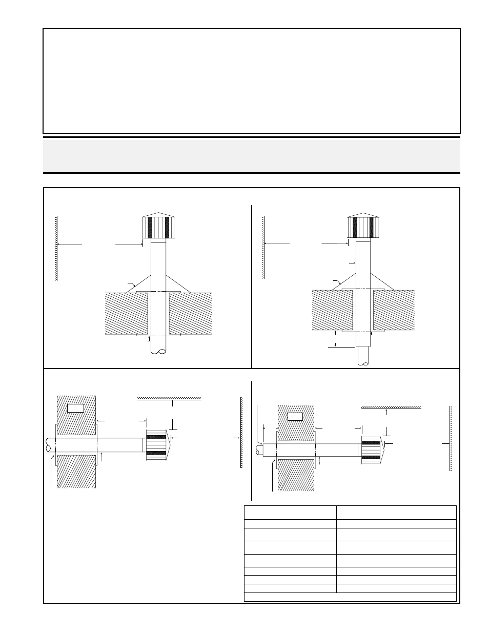
DANGER: Vent terminal arrangements illustrated are applicable only to units with a power
venter. Horizontal vent termination requires a power venter. DO NOT use a horizontal vent
with a gravity-vented heater.
Single-wall vent run and single-wall terminal end
Single-wall vent run and double-wall terminal end
VERTICAL Vent Terminal
FIGURE 15 - Vent Terminal Arrangements
Roof -
pitched
from
0 to 45°
A clearance thimble is
required when flue pipe
extends through combustible
materials. Follow the require-
ments of the double-wall pipe
manufacturer.
*Follow the instruc-
tions above to join
the double-wall vent
terminal section to
the vent run and to
seal the connection.
Vertical flue extension
must be 6 (152mm)
higher than anticipated
snow depth but no less
than 2 ft (610mm)
above the roof.
Roof Flashing
6 (152mm) minimum
Parapet or
Adjoining Building
6 ft (1.8M)
minimum
Double Wall Pipe*
Reznor
Option CC1
Vent Cap
Single-wall vent run and single-wall terminal end
Single-wall vent run and double-wall terminal end
HORIZONTAL Vent Terminal
HORIZONTAL VENT TERMINAL CLEARANCES:
The location of the termination of the horizontal vent sys-
tem must be in accordance with National Fuel Gas Code
Z223.1. Required minimum clearances are listed on the
right.
Products of combustion can cause discoloration of some
building finishes and deterioration of masonry materials.
Applying a clear silicone sealant that is normally used to
protect concrete driveways can protect masonry materials.
If discoloration is an esthetic problem, relocate the vent or
install a vertical vent.
A clearance thimble is required when flue pipe extends through combustible
materials. Follow the instructions of the thimble or vent pipe manufacturer.
Pitch flue pipe down toward
outlet 1/4 per foot for
condensate drainage. (NOTE: Slope
applies to entire horizontal vent run.)
18
(457 mm)
minimum
Wall
Roof or Building Overhang
3 ft (1M)
minimum
6 ft (1.8M) minimum
Reznor Option CC1Vent
Cap - note positions of
vent cap openings
(shaded areas)
Parapet or
Adjoining Building
A clearance thimble is required when flue pipe extends through combustible
materials. Follow the requirements of the double-wall pipe manufacturer.
Pitch flue pipe down toward
outlet 1/4 per foot for
condensate drainage. (NOTE: Slope
applies to entire horizontal vent run.)
18
(457 mm)
minimum
Wall
Roof or Building Overhang
3 ft (1M)
minimum
6 ft (1.8M) minimum
Reznor Option CC1
Vent Cap - note positions
of vent cap openings
(shaded areas)
Parapet or
Adjoining Building
Double-Wall
Vent Pipe*
*Follow the instructions above to join the
double-wall vent terminal section to a single-
wall vent run and to seal the connection.
6 (152mm) minimum
Structure
Minimum Clearances for Vent Termination
Location (all directions unless specified)
Forced air inlet within 10 ft (3.1m) 3 ft (0.9M) above
Combustion air inlet of another
appliance
6 ft (1.8M)
Door, window, or gravity air inlet
(any building opening)
4 ft (1.2M) horizontally; 4 ft (1.2M) below;
1 ft (.3M) above
Electric meter, gas meter * and
relief equipment
4 ft (1.2M) horizontally
Gas regulator *
3 ft (0.9M)
Adjoining building or parapet
6 ft (1.8M)
Grade (ground level)
7 ft (2.1M) above
*Do not terminate the vent directly above a gas meter or service regulator.