Reznor B Option - Power Venter Installation User Manual
Page 4
Form I-F/B-PV, Page 4
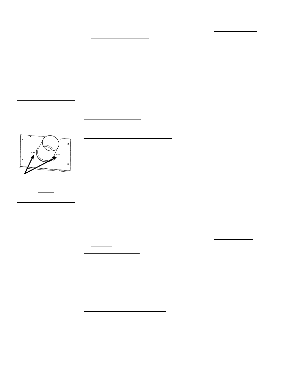
FIGURE 4B - Power
Venter Flue Adapter
for a Size 125 (plate
with a 4" flue collar)
Holes for attaching
1" x 7" restrictor
on the inside of the
assembly
(c) Install the Flue Adapter Assembly (FIGURE 4B) - applies to
Size 125
If the heater is installed, remove and discard the flue collar plate with the 7"
collar. Replace it with the venter flue adapter from the kit
with the restrictor
attached in Step 2.(a).
If the heater has not been installed, the flue outlet of a Size 125 heater
requires field assembly. To adapt the heater for power venting, the following
pieces are used:
•
Flue Collar Support provided with the heater
•
Flue Adapter Assembly provided in the optional power vent kit with the
restrictor attached in Step 2.(a) (See
FIGURE 4B.)
•
Flat Cover provided with the heater
NOTE: The flue collar assembly with the 7" oval collar provided with the heater
will not be used.
Refer to the instructions in the heater installation manual or Instruction
Form
I-F/B-HV125 in the standard vent outlet hardware bag. Attach the flue collar
support as instructed. Instead of attaching the standard flue collar assembly
with the 7" oval flue collar, attach the flue adapter assembly from the optional
venter kit (the flat plate with 4" collar and attached restrictor).
Attach the flat cover plate.
(d) Install the Flue Adapter Assembly - applies to Sizes 250, 300
and 400 (See FIGURE 4A, page 3.)
If the heater is installed, remove and discard the flue collar assembly and the
cover plate. Follow the instructions below to replace them with the venter flue
adapter from the kit
with the restrictor attached.
1) Position the flue adapter assembly from the option kit on the top of the
heater and center. Line up with the two holes on the back of the heater
(See
FIGURE 4A, page 3). Mark the three new screw holes on the top
of the heater.
2) Remove the adapter assembly and drill the holes with a 1/8" bit.
3) Attach the flue adapter assembly with five sheetmetal screws.
If the heater has not been installed, the flue outlet of Sizes 250, 300, and 400
heaters requires field assembly. But when adding the optional power venter,
none of the flue outlet pieces shipped with the heater are used. Remove the
two center screws (one of each side) that are holding the flue outlet pieces in
place for shipping.
Discard all three pieces and the parts bag.
1) Position the flue adapter assembly from the option kit on the top of the
heater and center. Line up with the two holes on the back of the heater
Installation
Instructions (cont'd)
2. Prepare and Install the Flue Adapter Assembly (cont'd)
(b) Install the Flue Adapter Assembly - applies to Sizes 25, 50, 75,
100, 130, 165, and 200 (See FIGURE 4A, page 3.)
1) Remove the factory-installed flue collar assembly and discard. (
NOTE:
If the heater was manufactured prior to 10/89, it has a fixed vertical vent
outlet so there is nothing to remove. Position the adapter assembly with
restrictor attached over the fixed vent outlet.)
2) Position the flue adapter assembly on the top of the heater (over the flue
outlet support) and center. Line up with the two holes on the back of the
heater. Mark the three new screw holes on the top of the heater.
3) Remove the adapter assembly and drill the holes with a 1/8" bit.
4) Attach the flue adapter assembly with sheetmetal screws.