0 maintenance and service, 0 commissioning and startup (cont’d), Inlet and exhaust components – Reznor MAPS IV Option - Installation - Energy Recovery Module Installation User Manual
Page 8: Energy recovery wheel
I-MAPSIII&IV-ER, PN262634R3, page 8
10.0 Maintenance
and Service
Exhaust Filters
Inlet Air Filters
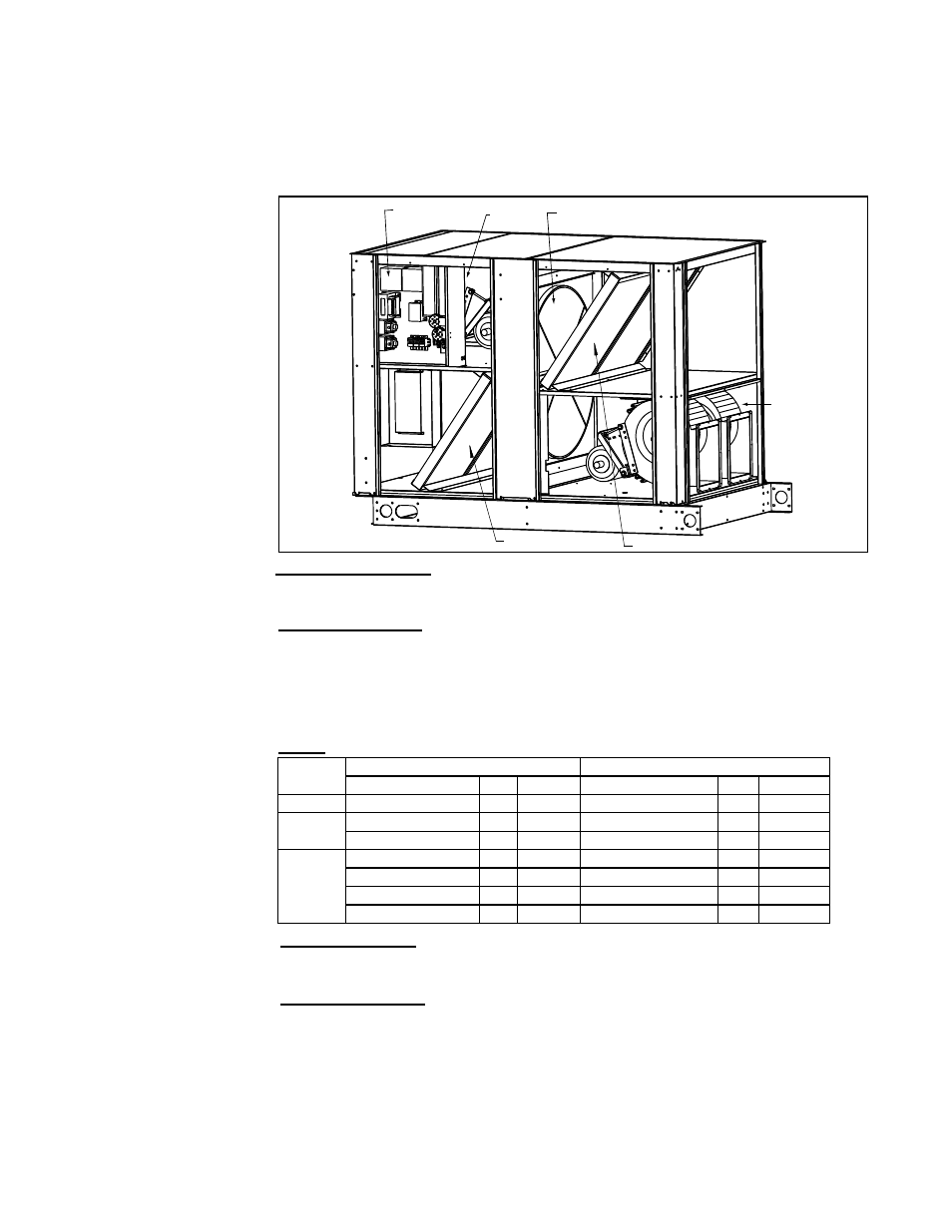
Energy Recovery Wheel - To access: (1) Remove center post;
(2) Disconnect motor wiring; (3) Slide out wheel cassette.
Exhaust
Fan(s)
Supply
Fan(s)
Control
Compartment
Center Post
(Remove to slide out the
wheel cassette.)
(Outside cabinet -
Location of
outside air hood
with cleanable
filters.)
(Inside
cabinet -
Location of
optional inlet
dampers.)
(Location of
gravity dampers
and exhaust
hood.)
(This end
connects
to the inlet
of a MAPS®
III or IV unit.)
Energy Recovery
Module with Panels and
Hoods Removed
Inlet and Exhaust
Components
Blowers and Drives - The blowers (supply and exhaust fans) have permanently lubri-
cated cartridge ball bearings and do not require greasing.
Check the condition and tension of the belts. Belt tension should allow a 3/4” depres-
sion of the belt. See belt tension in Paragraph 8.0. If the belt needs to be replaced, use
a factory-authorized replacement.
Check the setscrews; see Paragraph 8.0.
Energy Recovery
Wheel
Check Wheel RPM - The wheel should rotate slowly at approximately 53 rpm. If rota-
tion is not normal, see the wheel maintenance information that follows. Perform service
as needed and/or replace any defective parts.
Wheel Maintenance - The energy recovery wheel cassette is designed to be slid out
of the unit for inspection and cleaning. Follow the instructions in
the illustration on
page 7 and the cleaning instructions below.
How often the wheel needs to be cleaned depends on its environment. Because the
wheel rotates between two opposing airstreams, it is self-cleaning of most dry dirt and
dust and will remain efficient for a long period of time. However, when the wheel is
exposed to oils, tars, or greases in either the supply or exhaust airstream, the surface
will become “sticky” and will hold the dirt and dust. Over time the air passages will
become blocked causing loss of recovery, excessive pressure drop, and loss of energy
savings.
Filters - Check inlet and exhaust filters. Replace as needed.
Cabinet
Size *
Inlet Air Filters (Merv 8)
Exhaust Air Filters (Merv 8)
Filter Type & Size
Qty
P/N
Filter Type & Size
Qty
P/N
A
Pleated 20x25x2
2
104113
Pleated 20x25x2
2
104113
B
Pleated 16x25x2
2
104112
Pleated 16x25x2
2
104112
Pleated 12x25x2
2
114320
Pleated 12x25x2
2
114320
C
Pleated 16x25x2
2
104112
Pleated 16x25x2
2
104112
Pleated 20x25x2
2
104113
Pleated 20x25x2
2
104113
Pleated 16x16x2
1
104109
Pleated 16x16x2
1
104109
Pleated 16x20x2
1
104110
Pleated 16x20x2
1
104110
*See cross-reference of
MAPS
®
Models by Cabinet
Size A, B, or C on page 11.
Hoods and Dampers - Clean the filters in the outside air hood. If there is an inlet
damper, carefully remove dirt from the damper blades. Clean gravity relief damper
blades at the exhaust outlet.
□
If equipped with dirty filter switch (Option BE28), set the switch. See Paragraph
6.0.
□
After at least 8 hours but no longer than a week of operation, recheck the supply
and exhaust fan components -- blower wheels including all set screws, blower
pulleys, motor pulleys, and belt tension. Make any required adjustments. See
instructions and requirements in Paragraph 8.0.
9.0 Commissioning
and Startup
(cont’d)
Checks after Startup (cont’d)